3-19
D Example of Inching Operation (Set Value: 11)
Frequency
reference
Forward
rotation/Stop
Inching
command
Inching
operation
reference
Inching operation
reference
Frequency
reference
1
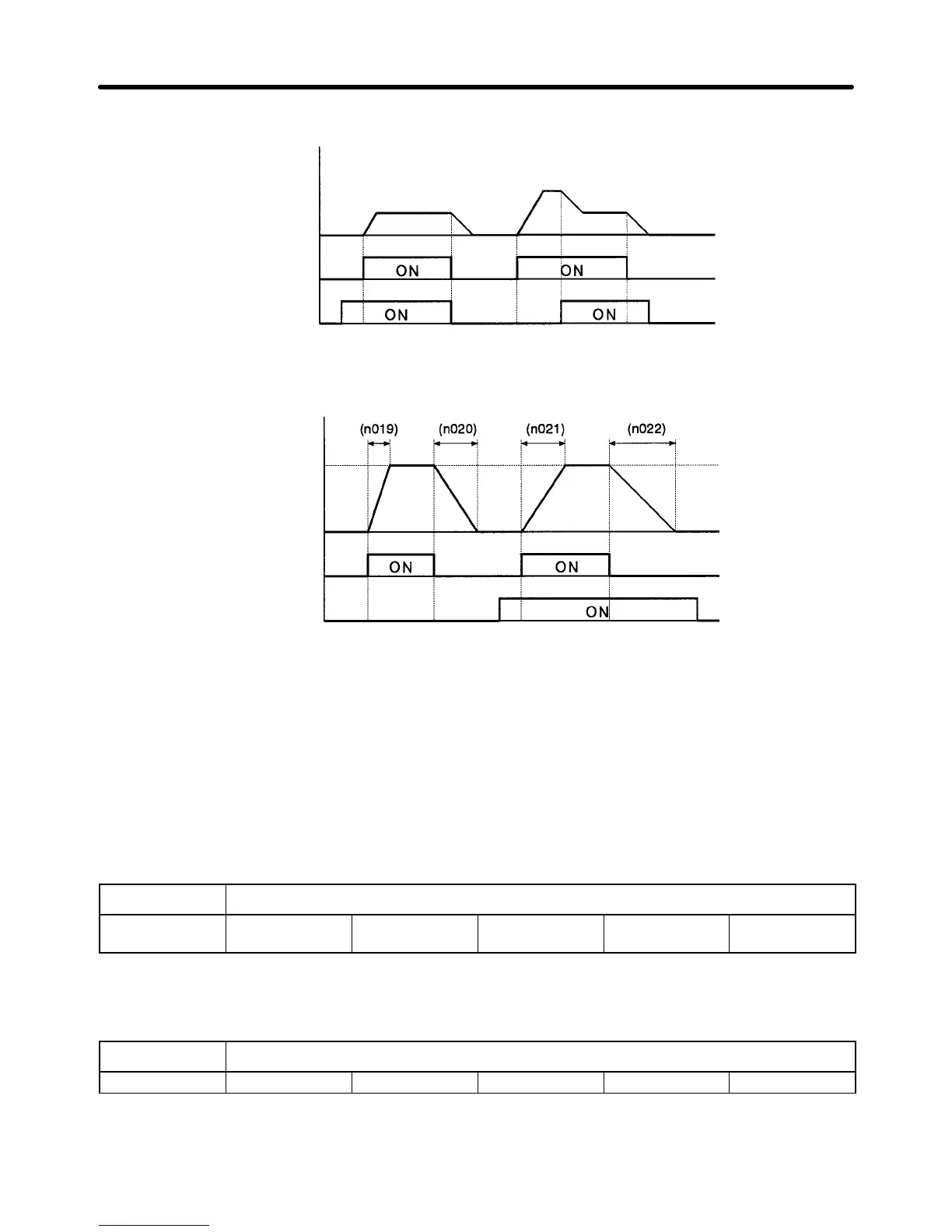
D Example of Acceleration/Deceleration Time Switching (Set Value 12)
Frequency
reference
Forward
rotation/Stop
Acceleration/
Deceleration
time switching
Maximum
frequency
(n012)
Acceleration
time
1
Deceleration
time 1
Acceleration
time 2
Deceleration
time 2
Note The
acceleration time and deceleration time of the Inverter will be switched the
moment the accel
-
eration/deceleration
time
switching command is input while the Inverter is accelerating or decel
-
erating the motor.
H V/f Pattern Selection (n010 to n018)
S Set the V/f pattern according to the characteristics of the mechanical system.
S Set
the rated input
voltage of the motor with n01
1 according to the rated input voltage of the motor
before setting the V/f pattern. This set value will be used to calculate the voltage axis of the V/f
pattern.
n011 Motor Rated Voltage
Setting range 150.0 to 255.0
(510.0)
Unit V Default setting 200.0 (400.0)
Note The figures in the parentheses apply to the 400-V Inverter.
S Set the V/f pattern.
n010 V/f Pattern Selection
Setting range 0 to F Unit --- Default setting 1
Set Values
S The following two methods are available to set the V/f pattern.
Preparing for Operation Chapter 3
 Loading...


