3-13
3-4 Basic Operation
Refer
to the following for the basic settings required to start and stop operating the In
-
verter. Only these settings are required for the Inverter in basic operation. These set-
tings
as well as other settings are required by the Inverter for any applied operation, such
as energy-saving control or PID control.
H Parameter Write Prohibit Selection (n001)
S The parameters used by the Inverter are classified into the following three groups.
Group 1: n001 to n034
Group 2: n035 to n049
Group 3: n050 to n108 (Up to n102 can be used.)
S The
Inverter is default-set so that only parameters of group 1 can be set and checked and the pa
-
rameters of groups 2 and 3 can only be checked.
S The
Inverter in basic operation uses the parameters
of groups 1 and 2. Therefore, set n001 to 2 or
3 so that these parameters can be checked and set.
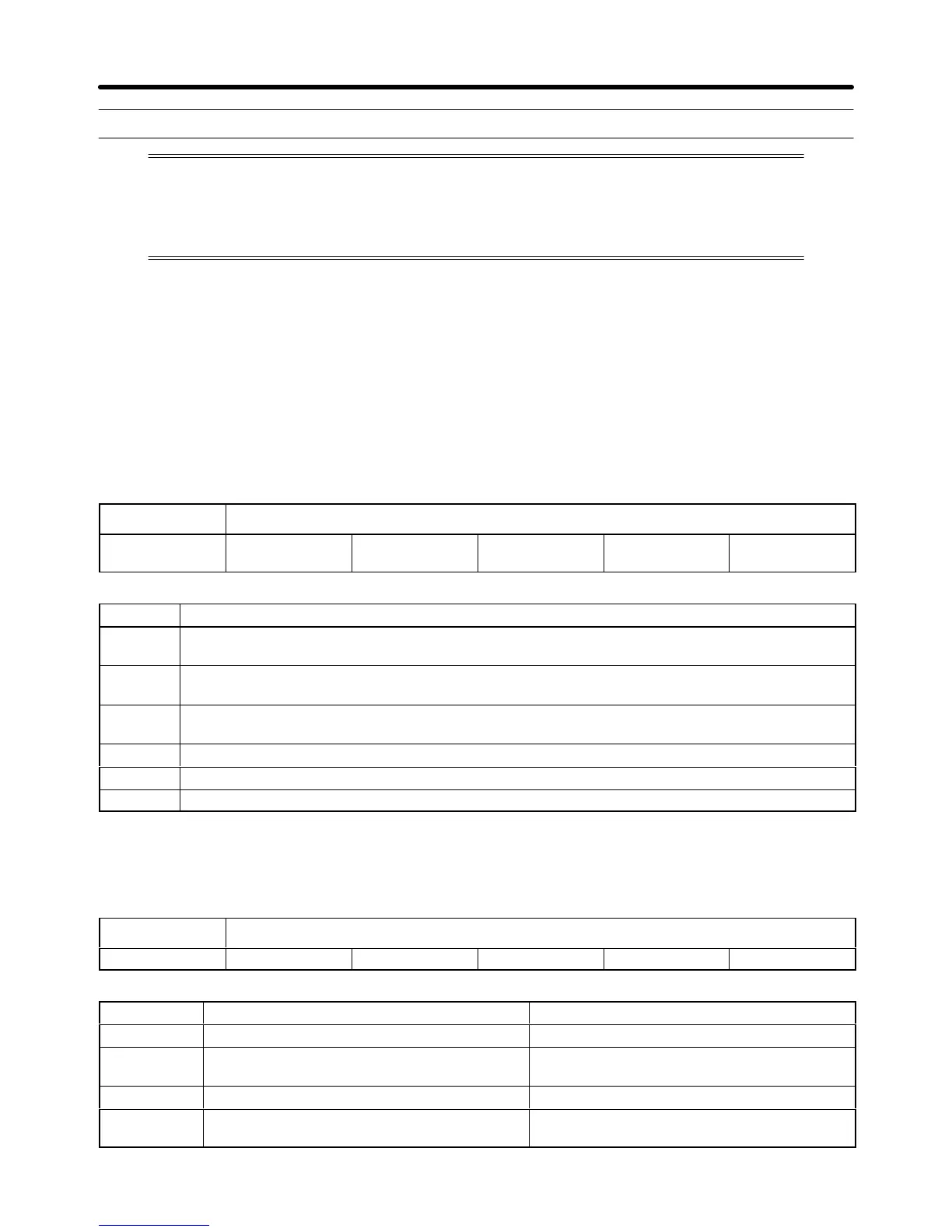
n001 Parameter Write Prohibit Selection/Parameter Initialization
Setting range 0, 1, 2, 3, 6, and
7
Unit --- Default setting 1
Set Values
Set value Description
0 The parameters n001 can be set and checked and the parameters n002 to n108 can be only
checked.
1 The parameters of group 1 (i.e., n001 to n034) can be set and checked and the parameters of
groups 2 and 3 (i.e., n035 to n049 and n050 to n108) can be only checked.
2 The parameters of groups 1 and 2 can be set and checked and the parameters of group 3 can
only be checked.
3 The parameters of groups 1, 2, and 3 can be set and checked.
6 All parameters will be set to default-set values.
7 All parameters will be initialized with a three-wire sequence.
Note Do not set n001 to any value other than the above.
H Operation Mode Selection (n002)
S The Inverter has four operation modes. Select one of the modes with n002.
n002 Operation Mode Selection
Setting range 0 to 3 Unit --- Default setting 3
Set Values
Set value Run command Frequency reference
0 Digital Operator (RUN/STOP Key) Digital Operator (Frequency reference 1)
1 Control circuit terminals
(Forward/reverse/stop input)
Digital Operator (Frequency reference 1)
2 Digital Operator (RUN/STOP Key) Control circuit terminals (Analog input)
3 Control circuit terminals
(Forward/reverse/stop input)
Control circuit terminals (Analog input)
Preparing for Operation Chapter 3
 Loading...


