4-2
4-1 Protective and Diagnostic Functions
H Errors Interrupting Inverter Output
• If
the Inverter detects an error
, the Inverter will have an error contact output and decelerate the motor
to
a stop, make the motor coast to a stop, or let the motor continue rotating according to the error pro
-
cessing mode selected while the Digital Operator displays the status of the error.
• If an error results, refer to the following and take the necessary action.
• Before
restarting
the Inverter
, take one of the following actions to reset the Inverter
. If the run signal is
ON, turn it OFF. The reset signal will be ignored if the run signal is ON.
Turn
ON an error reset signal by setting the multi-function input parameter used by the Inverter to 4.
Press the STOP/RESET Key.
Turn the main circuit power supply OFF and ON.
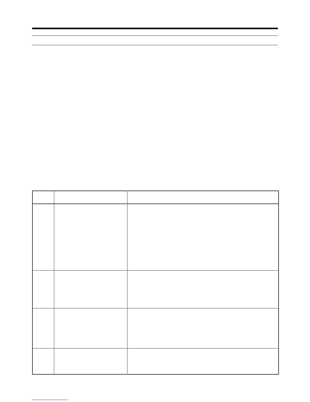
D Errors and Actions Taken
Data
display
Description Cause and action
%c Overcurrent (OC)
The Inverter output current
instantaneously exceeded the
overcurrent detection level.
The output side of the Inverter is shorted or grounded due to
motor coil burnout, poor motor coil insulation, or cable damage.
The load is excessive. The acceleration and deceleration time
settings are too short.
A special motor or a motor with a capacity exceeding the
maximum output capacity of the Inverter is used.
The magnetic contactor on the output side of the Inverter was
opened and closed.
→ Determine the cause of the error, take the necessary action,
and reset the system.
gf Ground fault (GF)
A ground fault current
exceeding 50% of the rated
Inverter output current flowed
from the output side of the
Inverter.
The output side of the Inverter is grounded due to the motor coil
burnout, poor motor coil insulation, or cable damage.
→ Determine the cause of the error, take the necessary action,
and reset the system.
puf Fuse pre-arcing (PUF)
The fuse of the main circuit
blew out.
The output transistor is broken, in which case replace the
Inverter. The output transistor will break if the B1 or negative
terminal is shorted with the T1 (U), T2 (V), or T3 (W) terminal.
The output side of the Inverter is shorted or grounded.
→ Determine the cause of the error, take the necessary action,
and reset the system.
sc Load short-circuit (SC)
The Inverter output or load is
shorted.
The output side of the Inverter is shorted or grounded due to
motor coil burnout, poor motor coil insulation, or cable damage.
→ Determine the cause of the error, take the necessary action,
and reset the system.
Operation Chapter 4
 Loading...


