2-32
• Input Transformers for 12-pulse Rectification
Refer
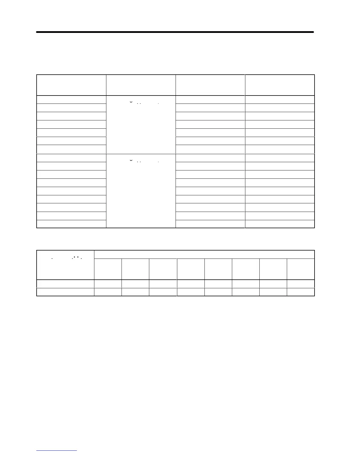
to the following table to select the input transformer for 12-pulse rectification. Refer to the mini
-
mum
currents on the secondary winding side in the table
when selecting two standard transformers
used in combination for 12-pulse rectification.
Inverter model
3G3HV-
Input voltage (V) Minimum current on
the primary winding
side (A)
Minimum current on
the secondary winding
side (A)
B2185
I/O voltage ratio: 1:1
100 50
B4450 120 60
B4550 180 80
B4750 206 103
B411K 280 140
B416K 380 190
• 12-pulse Rectification Effect
Harmonics are suppressed effectively with 12-pulse rectification as shown in the following table.
Harmonic suppres-
sion method
5th har-
monic
7th har-
monic
11th
harmon-
ic
13th
harmon-
ic
17th
harmon-
ic
19th
harmon-
ic
23th
harmon-
ic
25th
har-
monic
No reactor 65 41 8.5 7.7 4.3 3.1 2.6 1.8
12-pulse rectification 5.43 5.28 5.40 5.96 0.69 0.19 1.49 1.18
H Braking Resistor Unit and Braking Unit
• Connect the Braking Resistor Unit and Braking Unit to the Inverter as shown in the following.
• Set
n079 to 0 (i.e., no overheating protection of the Braking Resistor Unit) and n070 to 0 (i.e., no decel
-
erating stall prevention) before using the Inverter with the Braking Resistor Unit connected.
Note 1. Set n079 to 0 before operating the Inverter with the Braking Resistor Unit without thermal
relay trip contacts.
Note 2. The
Braking Resistor Unit cannot be used and the deceleration time cannot be shortened by
the Inverter if n070 is set to 1 (i.e., decelerating stall prevention).
• To
prevent the Unit from overheating, make a power supply sequence as shown below or connect the
thermal relay trip output of the Unit to the remote error input terminal of the Inverter to interrupt the
operation of the Inverter.
• The Braking Resistor Unit or Braking Unit cannot be connected to the Inverter with an output of
18.5 kW to 160 kW.
Installation Chapter 2
 Loading...


