3-12
S Press the Mode Key until the V/F indicator is lit.
S The following two methods are available to set the V/f pattern.
S Select
one of the fixed 15
V/f patterns preset with the Inverter
, in which case set the V/f pattern
to 0, 1, 2, 3, 4, 5, 6, 7, 8, 9, A, b, C, d, or E.
S Set the V/f pattern to F for an optional V/f pattern.
S The
following are the fixed V/f patterns preset
with the Inverter
. Refer to
3-4 Basic Operation
for
details.
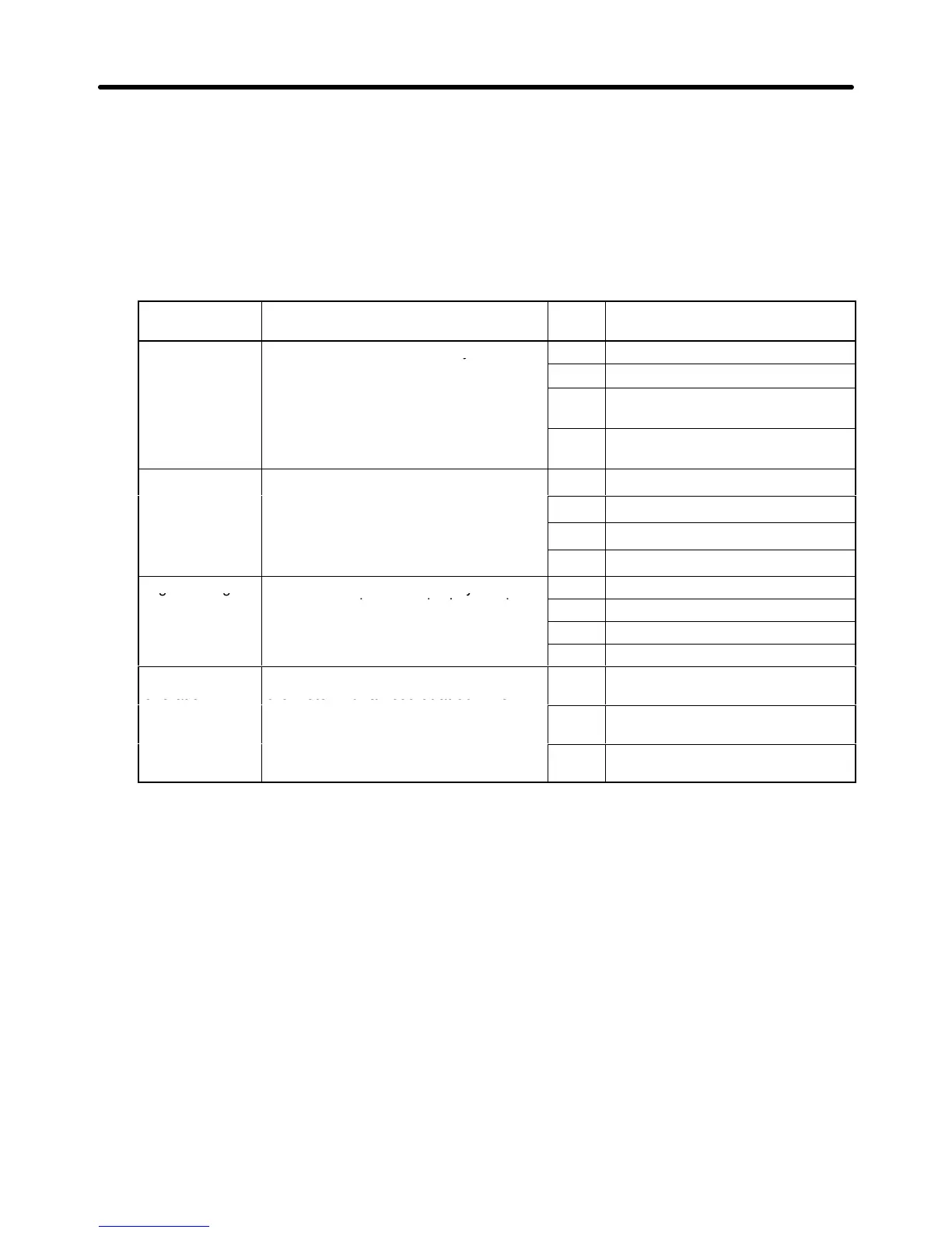
Characteristic Use Set
value
Specification
General These V/f patterns are mainly used for
general purposes, such as the control
of straight conveyor lines A
V/f patterns to the motor if the rotation
speed of the motor must chan
e in
2 60 Hz. Voltage saturation at
50 Hz.
s eed of the motor must change in
almost direct proportion to the load
factor of the motor.
3 72 Hz. Voltage saturation at
60 Hz.
Reduced
These V/f patterns are mainly used for
4 50 Hz with cube reduction.
torque fan pumps. Apply these V/f patterns to
the motor if the rotation speed of the
5 50 Hz with square reduction.
the motor if the rotation s eed of the
motor must change in square or cube
p
ortion to the load factor of the
6 60 Hz with cube reduction.
propor
e
motor.
7 60 Hz with square reduction.
High starting These V/f patterns are usually
8 50 Hz with low starting torque.
unnecessary because the Inverter has
a full automatic torque boost function to
9 50 Hz with high starting torque.
a
ull automatic torque boost
A 60 Hz with low starting torque.
su ly enough ower to meet the
starting torque of the motor.
B 60 Hz with high starting torque.
Constant power
operation
These V/f patterns are used to rotate
the motor with an output at 60 Hz or
C 90 Hz. Voltage saturation at
60 Hz.
t e oto t a out ut at 60 o
more. Apply these V/f patterns to the
motor to impose a constant voltage at
D 120 Hz. Voltage saturation at
60 Hz.
60 Hz min. on the motor.
E 180 Hz. Voltage saturation at
60 Hz.
S Select a V/f pattern suited to the mechanical system from the above V/f patterns.
S Set
the V/f pattern to F for an optional V/f pattern to be determined with n012 to n018. The optional
V/f pattern set with the Inverter before shipping is the same as the V/f pattern obtained with the set
value 1.
10. Operation with Actual Load
S Be ready to press the STOP/RESET Key for any error operation of the Inverter or the load.
S Use
the Digital
Operator to operate the Inverter in the same way as the operation of the Inverter
with no load.
S Set
the frequency reference so that
the motor will rotate at an approximately 10% of the rotation
speed of the motor in actual operation.
S Set
the frequency reference according to the actual rotation speed of the motor after making sure
that the mechanical system operates correctly and smoothly.
S Change the frequency reference and the rotation direction of the motor and check that the me-
chanical system operates without error vibration or noise.
Preparing for Operation Chapter 3
 Loading...


