1-6
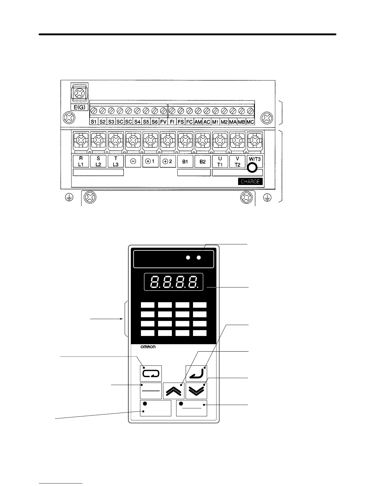
D Terminals (with Front Cover Removed)
Example: 200-V Class Inverter with 3.7-kW Output
Power
input
Braking
Resistor
Motor
output
Control
circuit
terminals
Main circuit
terminals
H Digital Operator
Easy-setting
indicators
Displays basic parameter
constants and monitor items.
Mode Key
Switches basic parameter
constant and monitor items.
Operation Mode Selection Key
Switches between operation by
the Digital Operator and operation
specified in the operation mode
selection parameter (n002).
Run Key
Starts the Inverter
.
Operation Mode Indicators
External Operation:
Lit when operating references from exter
-
nal terminals are in ef
fect.
Analog Input:
Lit when high-frequency references from
external analog terminals are in ef
fect.
Data Display
Displays frequency reference, out
-
put frequency
, output current,
constant set values, Inverter status,
etc.
Enter Key
Enters set value when pressed after
constant has been set.
Increment Key
Increments numbers when pressed
during setting of constant number
and constant data.
Decrement Key
Decrements numbers when
pressed during setting of constant
number and constant data.
Stop/Reset Key
Stops the Inverter
. Also resets after
alarm has been generated. (See note.)
DIGITAL OPERATOR PJVOP131E
Fref Fout Iout kWout
F/R Montr Accel Decel
Vmtr V/F Fgain Fbias
FLA PID kWsav PRGM
LOCAL
REMOTE
RUN
STOP
RESET
REMOTE
SEQ REF
Note For
safety reasons, the reset function cannot be
used while the run command (forward/reverse) is
being input. Turn the run command OFF before using the reset function.
Introduction Chapter 1
 Loading...


