2-18
2-2-4 Wiring Around the Main Circuit
System
reliability
and noise resistance are af
fected by the wiring method used. There
-
fore,
always follow the instructions given below when connecting the Inverter to periph
-
eral devices and other parts.
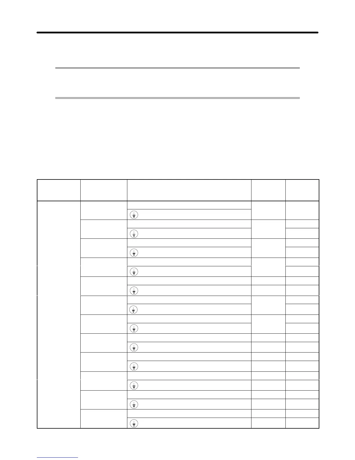
H Wire Size and Round Solderless Terminal
For the main circuit and ground, always use 600-V polyvinyl chloride (PVC) cables.
If
the cable is long and may cause voltage drops, increase the wire size
according to the cable length.
D Wire Sizes
Voltage class Model Terminal Terminal
screw
Wire
thickness
(mm
2
)
200-V Class 3G3HV-A2037
L1, L2, L3, (–), (+)1, (+)2, B1, B2, T1, T2, T3
M4 5.5
3G3HV-A2055
L1, L2, L3, (–), (+)1, (+)2, B1, B2, T1, T2, T3
M5
8
5.5 to 8
3G3HV-A2075
L1, L2, L3, (–), (+)1, (+)2, B1, B2, T1, T2, T3
M5
8
5.5 to 8
3G3HV-A2110
L1, L2, L3, (–), (+)1, (+)2, (+)3, T1, T2, T3
M6
22
8
3G3HV-A2150
L1, L2, L3, (–), (+)1, (+)2, (+)3, T1, T2, T3 M8 30
M6 8
3G3HV-B2185
L1, L2, L3, L11, L21, L31, T1, T2, T3
M8
30
14
3G3HV-B2220
L1, L2, L3, L11, L21, L31, T1, T2, T3
M8
38
14
3G3HV-B2300
L1, L2, L3, L11, L21, L31, T1, T2, T3 M10 100
M8 22
3G3HV-B2370
L1, L2, L3, L11, L21, L31, T1, T2, T3 M10 60 x 2P
M8 22
3G3HV-B2450
L1, L2, L3, L11, L21, L31, T1, T2, T3 M10 60 x 2P
M8 22
3G3HV-B2550
L1, L2, L3, L11, L21, L31, T1, T2, T3 M10 60 x 2P
M8 30
3G3HV-B2750
L1, L2, L3, L11, L21, L31, T1, T2, T3 M12 100 x 2P
M8 50
Installation Chapter 2
 Loading...


