2-17
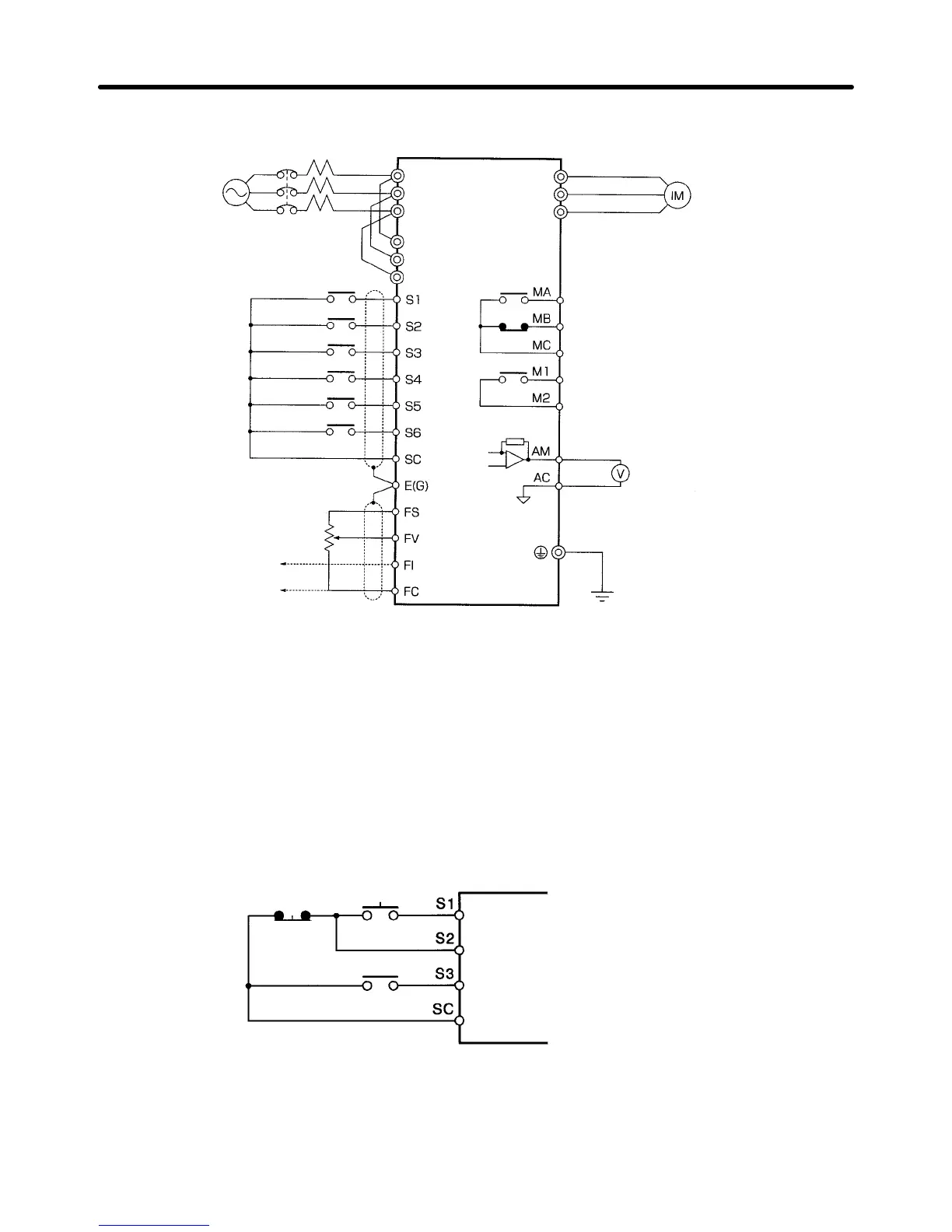
D For Inverter Models of 200- to 400-V Class with 18.5- to 300-kW Output
Three-phase,
200 (400) VAC
Forward rotation/Stop
Multi-function
input
1
Multi-function
input 2
Multi-function
input 4
Multi-function
input 5
Multi-function
input 3
Common
Shielded wire
Variable resistor for
frequency reference
(voltage input)
Frequency
reference
(current input)
Note 1. The Braking Unit or Braking Resistor Unit cannot be connected to the Inverter
(18.5 kW to 160 kW). However, 185-kW to 300-kW models can be connected.
Note 2. Make sure that terminals R and R1, S and S1, and T and T1 are short-circuited.
These terminals are short-circuited
with short bars before shipping. Be sure to re
-
move the short bars, however, when using 12-pulse rectification.
Note 3. Terminals
L1
1 (R1), L21 (S1), and L31 (T1) are not available on the 185- to 300-kW
Inverters.
Note 4. The
185- to 300-kW Inverters do not have built-in DC
reactors, nor can DC reactors
be externally connected.
Three-phase induction
motor
Multi-function contact output 1
(Normally open contact)
(Normally closed contact)
Common
Common
Multi-function contact output 2
Common
Multi-function analog output
Voltmeter
L1 (R)
L2 (S)
L3 (T)
T1 (U)
T2 (V)
T3 (W)
L1
1 (R1)
L21 (S1)
L31 (T1)
See note 3
D Example of Wiring for 3-wire Sequential Operation
Stop switch
(NC)
Operation switch
(NO)
Run command (Operates when the
operation switch is closed)
Stop command (Stops when the stop
switch is open)
Forward/Reverse rotation command
Installation Chapter 2
 Loading...


