3-78
• Select
the FV terminal to input the frequency reference within a voltage range from 0
to 10 VDC or the
FI terminal to input the frequency reference within a current range from 4 to 20 mA with n042.
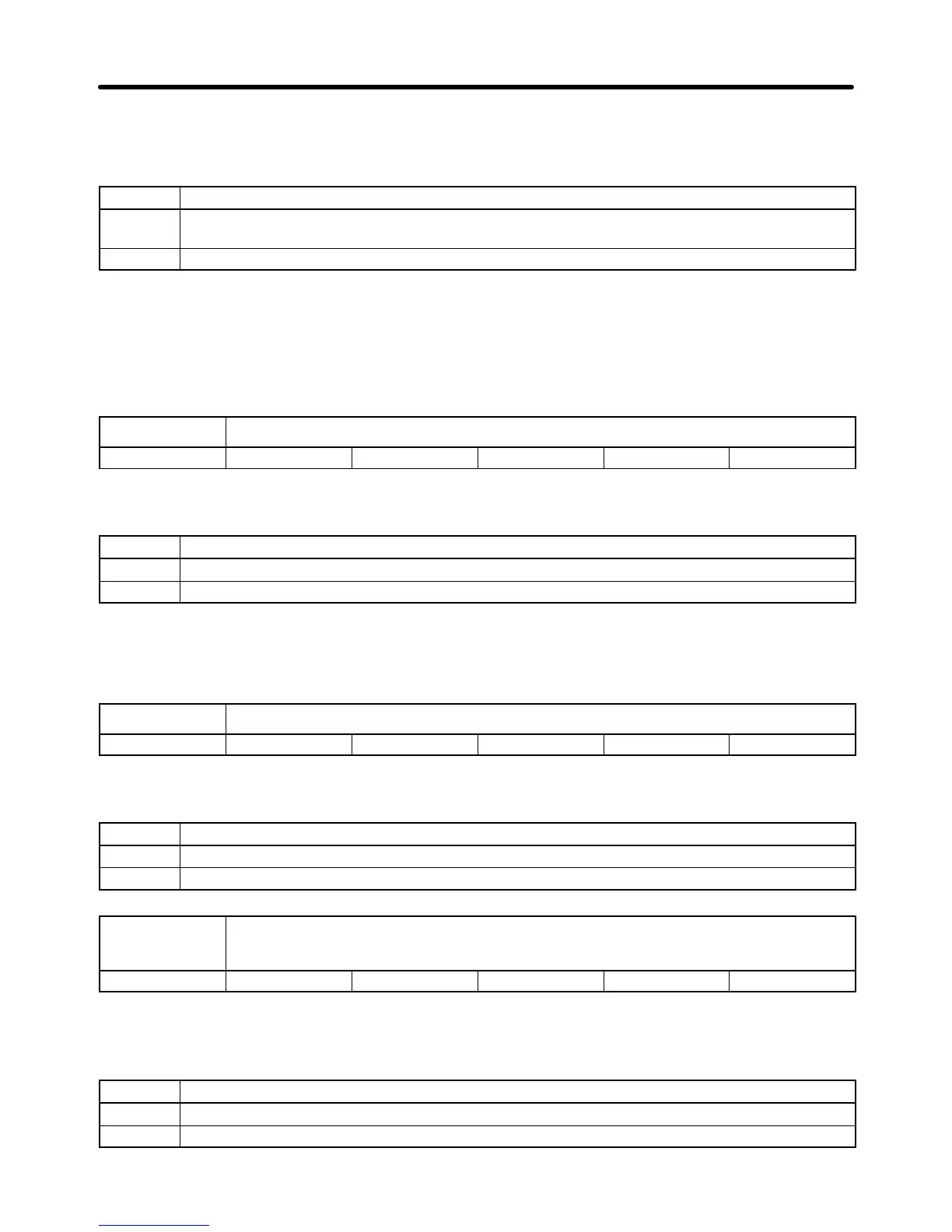
Set Values
Set value Description
0 The FV terminal can be used for the analog frequency reference within a voltage range from 0
to 10 VDC.
1 The FI terminal can be used for the analog frequency reference. Set the input level with n043.
Note 1. The
FI terminal is a current input terminal for 4 to 20 mA. The FI terminal can be a voltage input
terminal
by changing the FI input level with n043
and cutting the jumper wire of the PCB. Do
not,
however
, change the FI terminal to a voltage input terminal unless the Inverter is used
for
PID control.
Note 2. Set n042 according to the type of frequency reference.
n043 FI Input Level Selection
Setting range 0, 1 Unit --- Default setting 1
• Set the FI input level with n043 so that the FI terminal will become a current or voltage input.
Set Values
Set value Description
0 Voltage input within a range from 0 to 10 V. Be sure to cut jumper wire J1.
1 Current input within a range from 4 to 20 mA.
Note Do
not impose voltage on the Inverter without cutting jumper wire J1 if n043 is set to 0, otherwise
the input resistor of the Inverter will burn out.
Refer to
page 3-34
for the position of the jumper wire.
n044 Analog Frequency Reference Sample Hold Selection
Setting range 0, 1 Unit --- Default setting 0
• Set n044 when using the analog frequency sample and hold as multi-function input.
Set Values
Set value Description
0 Frequency reference on hold is saved by n025
1 Frequency reference on hold is not saved.
n045 Processing Selection when Analog Frequency Reference is
Lost
Setting range 0, 1 Unit --- Default setting 0
• Set
n045 to 0 or 1 to determine the
operation of the Inverter when the frequency reference input to the
FV or FI terminal drops sharply.
Set Values
Set value Description
0 Inhibits Inverter from processing analog frequency reference loss.
1 Permits Inverter to process analog frequency reference loss.
Preparing for Operation Chapter 3
 Loading...


