2-35
Note Do
not solder wires with the control circuit terminals if wires are used instead of solderless termi
-
nals. Wires may not contact well with the control circuit terminals or the wires may be discon-
nected from the control circuit terminals due to vibration if the wires are soldered.
D Round Solderless Terminals for Ground Terminal
Wire thickness
(mm
2
)
Terminal
screw
Size
0.5
M3.5
1.25 to 3.5
0.75 1.25 to 3.5
1.25 1.25 to 3.5
2 2 to 3.5
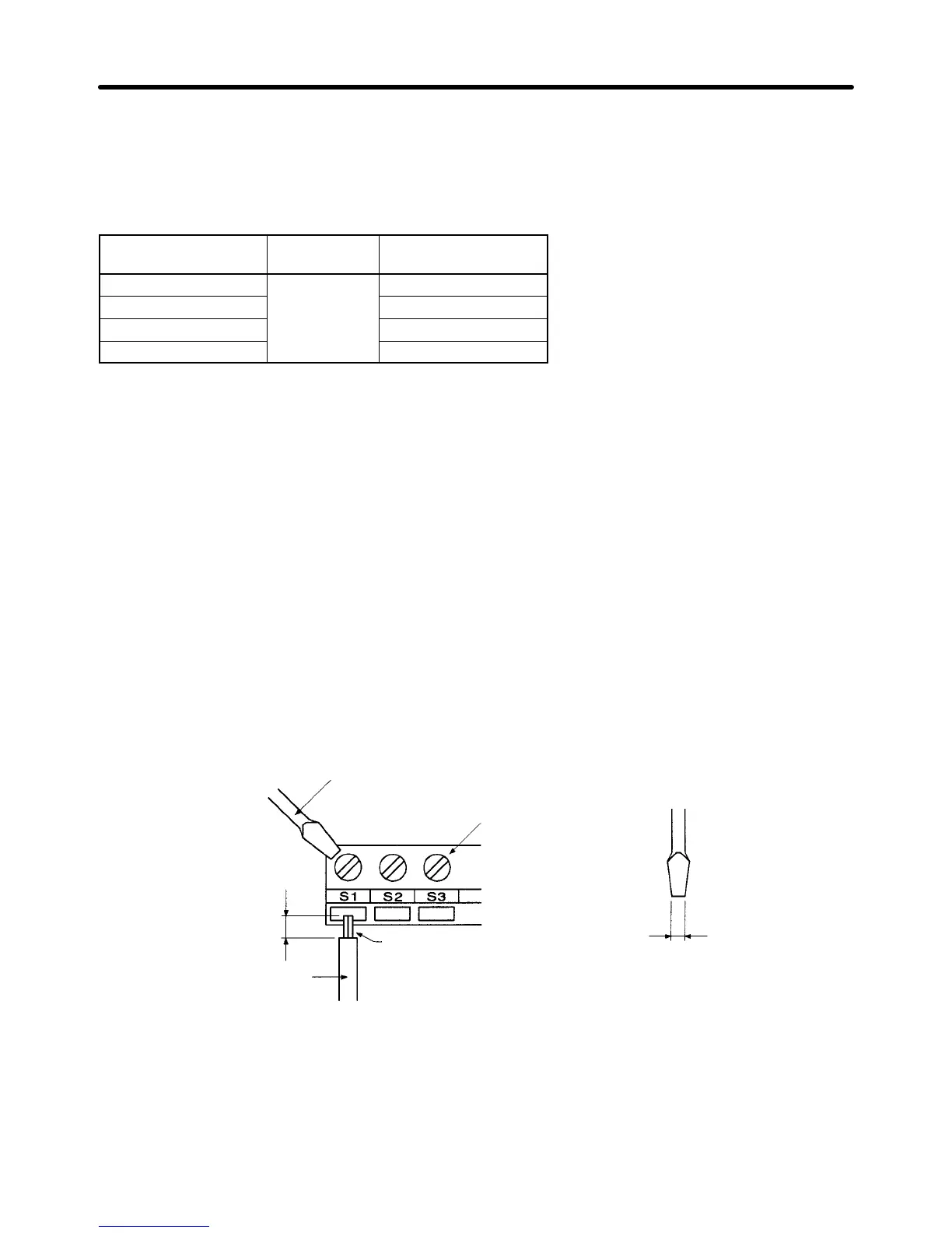
H Wiring Control Circuit Terminals
D Wiring Method
1. Loosen the terminal screws with a thin-slotted screwdriver.
2. Insert the wires from underneath the terminal block.
3. Tighten the terminal screws firmly.
Note 1. Always
separate the control signal line from the main circuit cables and other power cables.
Note 2. Do
not solder the wires to the control circuit terminals. The wires may not contact well with the
control circuit terminals if the wires are soldered.
Note 3. The
end of each wire connected to the control circuit terminals must be
stripped for approxi
-
mately 7 mm.
Note 4. Use a shielded wire for the ground terminal.
Note 5. Insulate the shield with tape so that the shield will not touch any signal line or device.
Strip
the end for 7 mm if
no solderless terminal is
used.
Wires
Thin-slotted screwdriver
Control circuit
terminal block
Solderless terminal or
wire without soldering
Blade of screwdriver
3.5 mm max.
Blade thickness: 0.6 mm max.
Note Tighten
screws to a torque between 0.5 and 0.6 N
S
m. T
ightening to a torque greater than this may
cause
the terminal block to be damaged.
T
ightening to a torque less than this may result in mal
-
function or short-circuiting.
Installation Chapter 2
 Loading...


