2-33
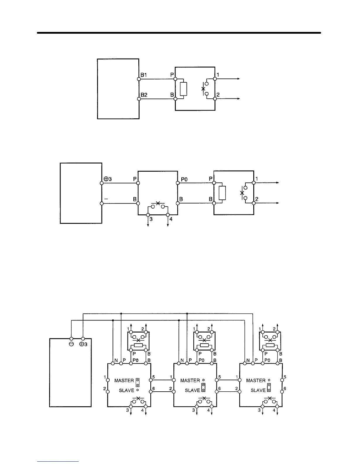
D 200-V Class with 3.7- to 7.5-kW Output and 400-V Class with 3.7- to 15-kW Output
Inverter
Braking Resistor Unit
Thermal relay
trip contact
D 200-V Class with 11- to 15-kW Output and 400-V Class with 185- to 300-kW Output
Inverter
Thermal relay
trip contact
Control Unit
Braking Resistor Unit
Thermal relay trip contact
D Connecting Braking Units in Parallel
When connecting two or more Braking Units in parallel, use the wiring and connectors shown in the
following diagram.
There are connectors for selecting whether each Braking Unit is to be a Master or
Slave.
Select “Master” for the first Braking Unit only; select “Slave” for all other Braking Units (i.e., from
the second Unit onwards).
Inverter
Thermal
relay trip
contact
Braking
Resistor
Unit
Braking Unit #1
Braking Unit #2
Braking Unit #3
Thermal
relay trip
contact
Thermal
relay trip
contact
Braking
Resistor
Unit
Thermal
relay trip
contact
Braking
Resistor
Unit
Thermal
relay trip
contact
Thermal
relay trip
contact
Installation Chapter 2
 Loading...


