3-33
H PID Control Function
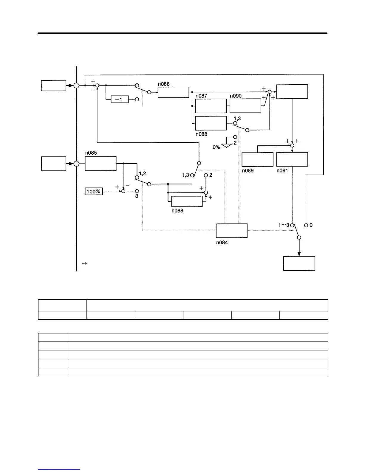
Refer to the following block diagram for the PID control performed by the Inverter.
Set
point
Feedback
FV
terminal
FI terminal
Feedback
ad
-
justment gain
100%:
Feedback value
corresponding to the
maximum frequency
(N012)
Inside the Inverter
Multi-function
input/PID input selection
Proportional
gain
1/Integral
time
Derivative
time
Upper
limit
of integral (I)
Internal
limit
±109%
PID of
fset
adjustment
PID
primary
delay
time constant
PID
control
selection
Inverter
fre
-
quency refer
-
ence
Derivative
time
H PID Control Settings
n084
PID Control Function Selection
Setting range 0, 1, and 2 Unit --- Default setting 0
Set Values
Set value Description
0 No PID control.
1 PID control with deviation derivative control.
2 PID control with feedback derivative control.
3 PID control with negative feedback characteristic control.
Note 1. Set n084 to 1, 2, or 3 to permit the Inverter to perform PID control.
Note 2. Usually set n084 to 2 to change set points.
Note 3. Set
n084 to
3 to perform PID control using the negative characteristic of the characteristic of
the
feedback value input from the sensor
. Using the negative characteristic means that [100%
–
feedback value] is used as the PID feedback value. This is ef
fective for negative characteris
-
tic control (control where the feedback value drops when the Inverter’s output frequency
rises).
Preparing for Operation Chapter 3
 Loading...


