3-34
• If
n084 is set to 1 or 2, the method to input the set point will be determined by the
operation mode set
with
n002 and the FI terminal will be used for feedback input. Set the FI input
level with n043 to select
current feedback input or voltage feedback input to the Inverter.
Input terminal
Operation mode selection (n002)
0 or 1 (Frequency reference: Digital
Operator)
2 or 3 (Frequency reference: Control
circuit terminals)
Set point input Frequency reference: n025 to n029 FV terminal: Voltage frequency reference
input
Feedback input FI terminal: Frequency reference input (default-set to current frequency reference input)
n043 FI Input Level Selection
Setting range 0, 1 Unit --- Default setting 1
Set Values
Set value Description
0 Voltage input within a range from 0 to 10 V. Be sure to cut jumper wire J1.
1 Current input within a range from 4 to 20 mA.
Note Do
not impose voltage on the Inverter without cutting jumper wire J1 if n043 is set to 0, otherwise
the input resistor of the Inverter will burn out.
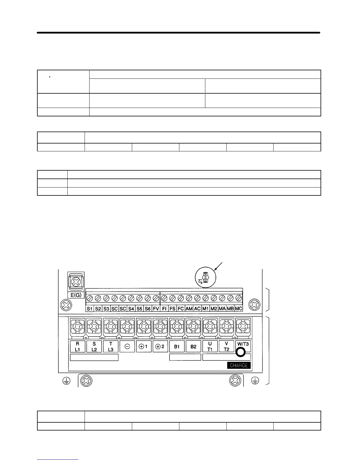
D 200 V, 3.7 kW
Jumper wire
Power input
Braking
Resistor
Motor
output
Control
circuit
terminals
Main circuit
terminals
n085 Feedback Adjustment Gain
Setting range 0.00 to 10.00 Unit Times Default setting 1.00
Preparing for Operation Chapter 3
 Loading...


