3-8
D Monitor Display Table
Monitor No. Monitor item Description
U-01 Frequency
reference
The frequency reference can be monitored. The display unit can be set
with n024. The frequency reference can be monitored with the FREF
indicator as well.
U-02 Output frequency The output frequency can be monitored. The display unit can be set
with n024. The output frequency can be monitored with the
FREQUENCY indicator as well.
U-03 Output current The output current can be monitored in 0.1-A units. The output current
can be monitored with 0.1-A units with the IOUT indicator as well.
U-04 Output voltage The output voltage can be monitored in 1-V units.
U-05 DC voltage The DC voltage can be monitored in 1-V units.
U-06 Output power The output power can be monitored in 0.1-kW units. The output power
can be monitored in 0.1-kW units with the POWER indicator as well.
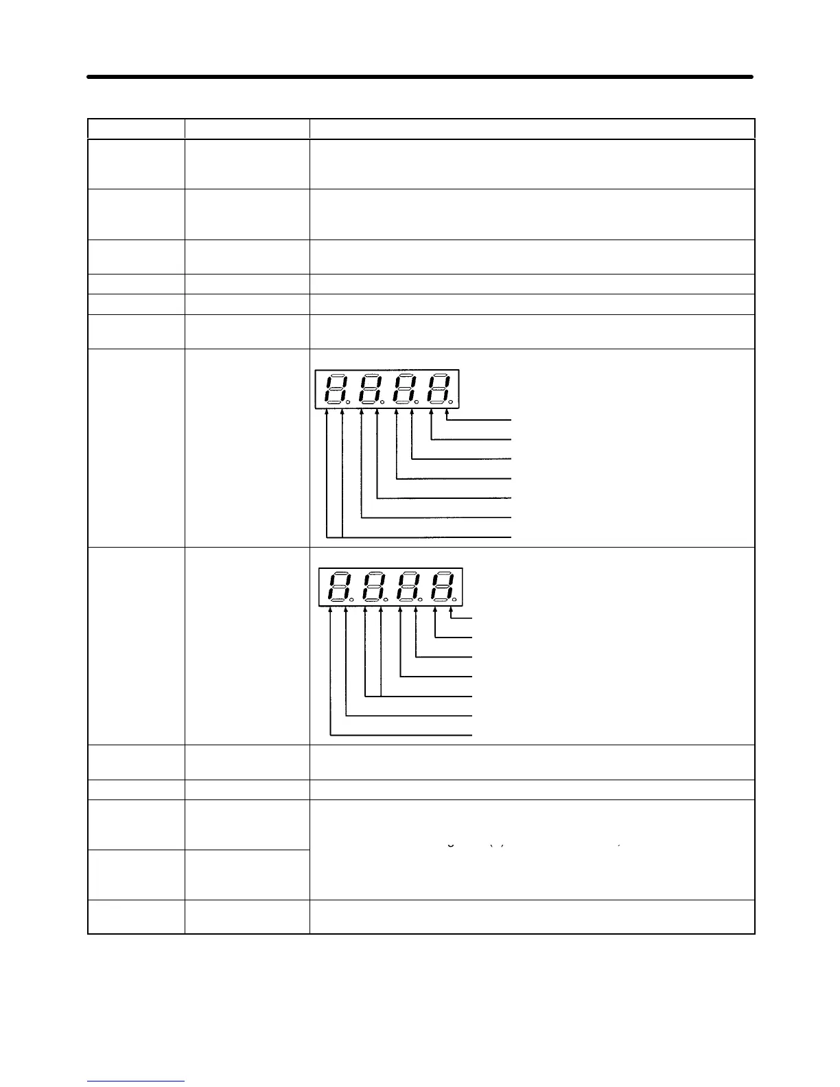
U-07 Input terminal
status
The statuses of input terminals S1 to S6 can be monitored.
Lit when S1 is ON.
Lit when S2 is ON.
Lit when S3 is ON.
Lit when S4 is ON.
Lit when S5 is ON.
Lit when S6 is ON.
Not used (Not lit).
U-08 Inverter status The status of the Inverter can be monitored.
Lit while the Inverter is running.
Lit when the reverse rotation command is given.
Lit when the Inverter is ready to operate.
Lit when the Inverter is error.
Not used (Not lit).
Lit when MA, MB, and MC outputs are ON.
Lit when outputs M1 and M2 are ON.
U-09 Error before
power interruption
The four most-recent errors before the power supplied to the Inverter is
turned OFF can be checked.
U-10 PROM number For the manufacturer’s use.
U-11 Total operating
time (rightmost 4
digits)
The accumulated operating time can be monitored with 1-h units. The
maximum value is 279,620 h.
Accumulated operating time (h) = U-12 value x 10,000 + U-11 value
U-12 Total operating
time (leftmost 2
digits)
U-13 PID feedback
value
The PID feedback can be monitored in 0.1-Hz units.
H Operation Mode Selection Key/Operation Mode Selection Input
The operation mode of the Inverter can be changed using the Operation Mode Selection Key on the
Digital
Operator
. Using this key
, it is possible to switch between the two operation modes shown below
.
Preparing for Operation Chapter 3
 Loading...


