2-24
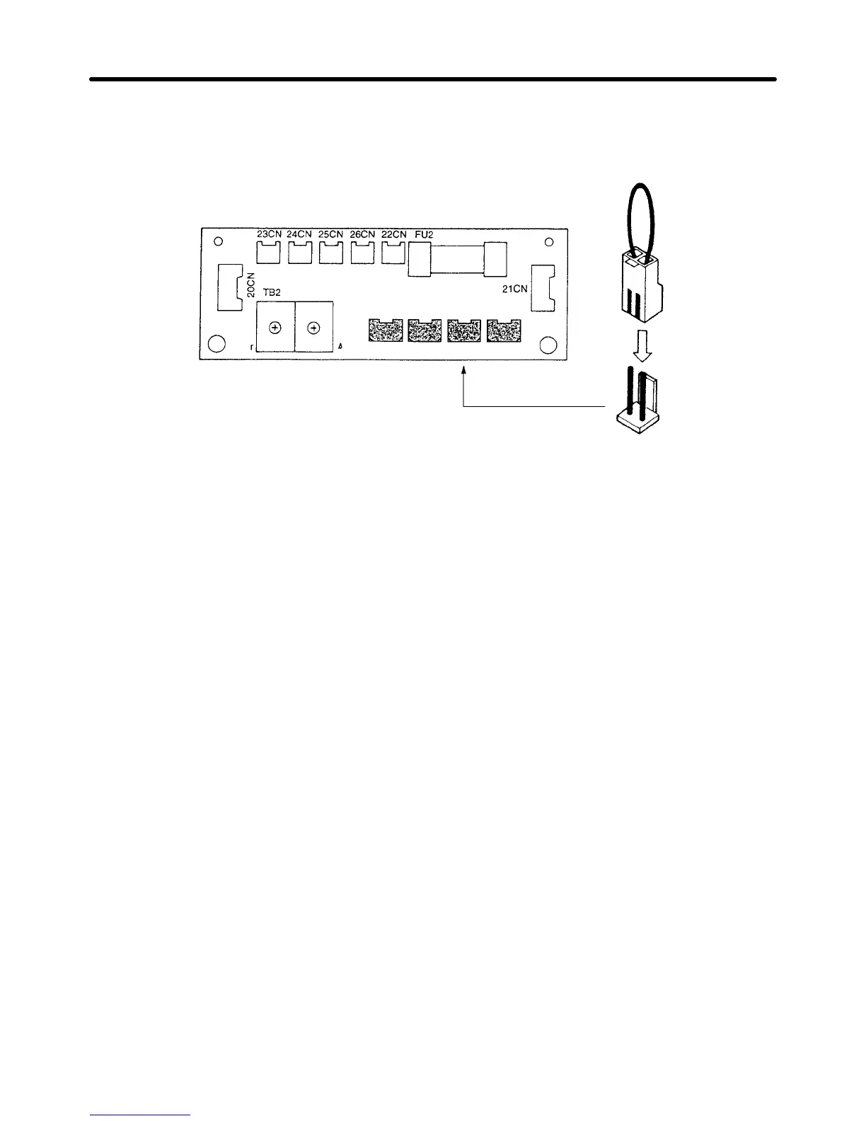
2. Insert the short pin mounted on the board into the voltage connector nearest to the actual power
supply voltage. The default setting is 440 V.
The following example shows board of a 400-V Class Inverter of 18.5 to 45 kW.
380 V 400/415 V 440 V 460 V
3. Put the front panel to its original position.
H Wiring on the Output Side of Main Circuit
D Connecting the Terminal Block to the Load
Connect output terminals T1 (U), T2 (V), and T3 (W) to motor lead wires T1 (U), T2 (V), and T3 (W),
respectively.
Check that the motor rotates forward with the
forward command. Switch over any two of
the output terminals to each other and reconnect if the motor rotates in reverse with the forward com
-
mand.
D Never Connect a Power Supply to Output Terminals
Never
connect a power supply to output terminals T1 (U), T2 (V), and T3 (W). If voltage is applied to the
output terminals, the internal circuit of the Inverter will be damaged.
D Never Short or Ground Output Terminals
If
the output terminals are touched with bare hands or the output wires come into contact with the Invert
-
er
casing, an electric shock or grounding will occur
. This is extremely hazardous. Also, be careful not to
short the output wires.
D Do Not Use a Phase Advancing Capacitor or Noise Filter
Never
to connect a phase advance capacitor or LC/RC noise filter to the output circuit. Doing so may
result in damage to the Inverter or cause other parts to burn.
D Do Not Use an Electromagnetic Switch or Magnetic Contactor
Do
not connect an electromagnetic switch or magnetic contactor to the output circuit. If a load is con
-
nected
to the Inverter during running, an inrush current will actuate the overcurrent protective circuit in
the Inverter.
Installation Chapter 2
 Loading...


