3-54
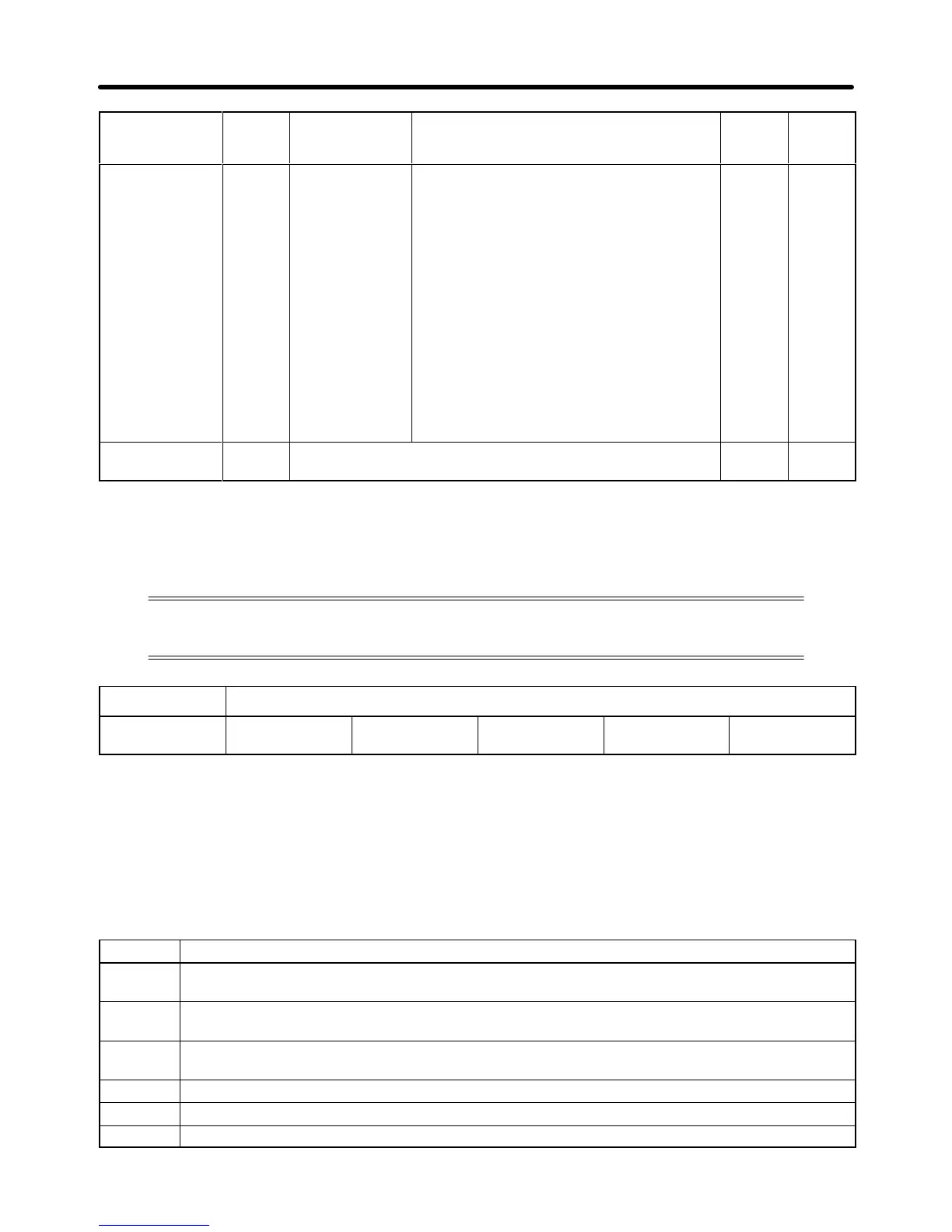
Function
Refer-
ence
page
Setting
range
DescriptionNameNo.
Operation
selection at
operation mode
switching (local/
remote switch-
ing)
n114 Operation
selection at
operation mode
switching (lo-
cal/remote
switching)
Select whether or not to ignore run signals
input while the operation mode is switched
using the Operation Mode Selection Key
on the Digital Operator or with operation
mode selection input from the multi-func-
tion inputs.
0: Run signals that are input during mode
switching are ignored. (Input run sig-
nals after switching the mode.)
1: Run signals become effective immedi-
ately after mode.
Note If
n1
14 is set to 1, when the operation
mode
changes the Inverter may start
running immediately. Take steps to
ensure safety for such operation.
0, 1 [0] 3-91
(Manufacturer’s
use)
n115,
n116
For the manufacturer’s use. (Do not set.) See
note
---
Note Setting ranges and default settings vary with the Inverter model.
3-5-4 Parameters in Detail
Refer to the following for the functions of the parameters used with the Inverter not in
energy-saving or PID control operation.
n001 Parameter Write Prohibit Selection/Parameter Initialization
Setting range 0, 1, 2, 3, 6, and
7
Unit --- Default setting 1
• The parameters used by the Inverter are classified into the following three groups.
Group 1: n001 to n034
Group 2: n035 to n049
Group 3: n050 to n108 (Up to n102 can be used.)
• The
Inverter is default-set so that only parameters of group 1 can be set and checked and the parame
-
ters of groups 2 and 3 can only be checked.
Set Values
Set value Description
0 The parameters n001 can be set and checked and the parameters n002 to n108 can be only
checked.
1 The parameters of group 1 (i.e., n001 to n034) can be set and checked and the parameters of
groups 2 and 3 (i.e., n035 to n049 and n050 to n108) can be only checked.
2 The parameters of groups 1 and 2 can be set and checked and the parameters of group 3 can
be only checked.
3 The parameters of groups 1, 2, and 3 can be set and checked.
6 All parameters will be set to default-set values.
7 All parameters will be initialized with a three-wire sequence. (see note 2)
Preparing for Operation Chapter 3
 Loading...


