3-74
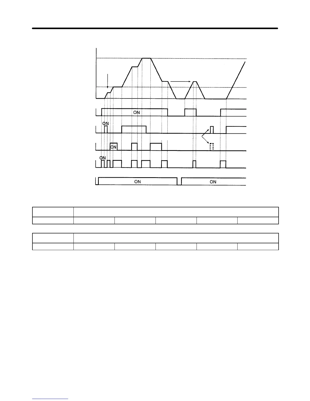
Operation Example
Output frequency
Upper limit
Lower limit
Output
frequency
will reach lower
limit with input to
S5 or S6.
Same frequency
Up command
(S5)
Down command
(S6)
Frequency
agreement signal
Note: The frequency synchronization signal is ON when the run command is ON
while the Inverter is not in acceleration or deceleration mode.
Power supply
Frequency
reference reset
Forward
rotation/Stop
(S1)
n040 Multi-function Contact Output 1 (MA-MB-MC)
Setting range 0 to 17 Unit --- Default setting 0
n041 Multi-function Contact Output 2 (M1-M2)
Setting range 0 to 17 Unit --- Default setting 1
• The
functions of multi-function contact output 1 (MA, MB, and MC) and multi-function contact output 2
(M1 and M2) can be selected from the following.
Preparing for Operation Chapter 3
 Loading...


