2-16
2-2-3 Standard Connection Diagram
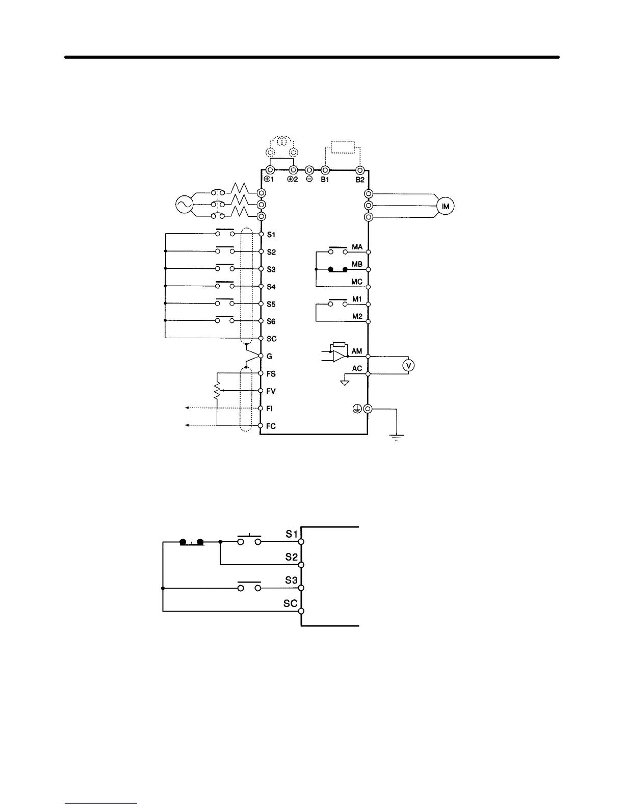
D For Inverter Models of 200- to 400-V Class with 3.7- to 15-kW Output
Three-phase,
200 (400) VAC
DC reactor (External
connection possible)
Forward rotation/Stop
Multi-function
input
1
Multi-function
input 2
Multi-function
input 4
Multi-function
input 5
Multi-function
input 3
Common
Shielded wire
Variable resistor for
frequency reference
(voltage input)
(2 kΩ, 1/4 W min.)
Frequency
reference
(current input)
Note: These terminals of the 3G3HV-A2110 and 3G3HV-A2150
connect to the Braking Unit and Braking Resistor Unit.
Braking Resistor Unit
(see note) (optional)
Three-phase induction
motor
Multi-function contact output 1
(Normally open contact)
(Normally closed contact)
Common
Common
Multi-function contact output 2
Common
Multi-function analog output
Voltmeter
L1 (R)
L2 (S)
L3 (T)
T1 (U)
T2 (V)
T3 (W)
D Example of Wiring for 3-wire Sequential Operation
Stop switch
(NC)
Operation switch
(NO)
Run command (Operates when the
operation switch is closed)
Stop command (Stops when the stop
switch is open)
Forward/Reverse rotation command
Installation Chapter 2
 Loading...


