3-37
Note Measure the response waveform so that the timing of the step input will be known.
2. Calculation of PID Parameters
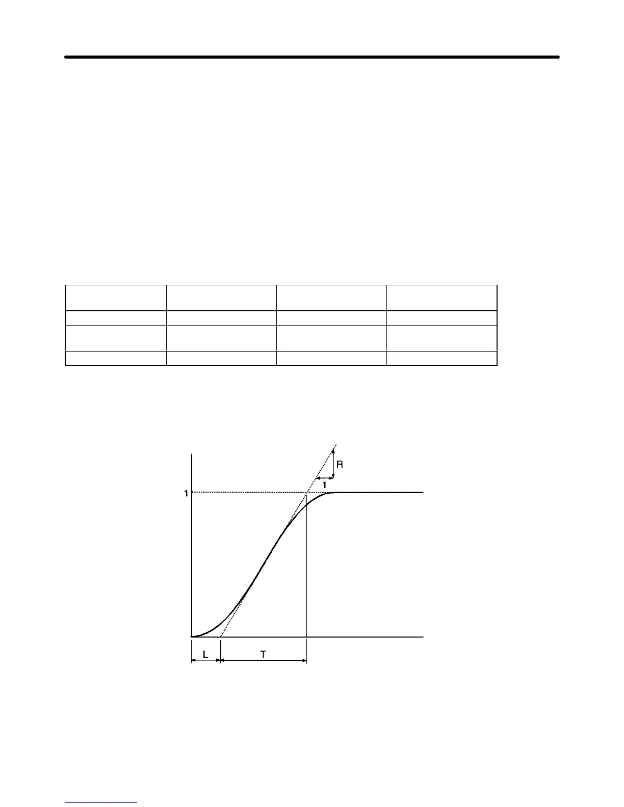
S Draw a tangent line contacting with the steepest inclining point of the response waveform.
S Measurement of R
Measure the gradient of the tangent line provided that the set point is 1.
S Measurement of L
Measure
the required time (seconds) between the origin and the point of intersection of the tan
-
gent line and time axis.
S Measurement of T
Measure
the required
time (seconds) between the point of intersection of the tangent line and time
axis and the point of intersection of the tangent line and set point line.
S PID Parameters
The following can be calculated from the R, L, and T values as “rules of thumb.”
Control Proportional gain (P)
(n086)
Integral time (I)
(n087)
Derivative time (D)
(n088)
Proportional control 0.3/RL --- ---
Proportional/Integral
control
0.35/RL 1.2T ---
PID control 0.6/RL T 0.5L
Note 1. Obtain
PID parameter values from the above
method, set the PID parameters, and tune in the
PID parameter values exactly.
Note 2. PID
parameter values
obtained from the above method may not be optimum values if the fric
-
tion factor of the mechanical system is large.
Response
Time
Set
point
D Manual Adjustments
Take
the following steps
to adjust the PID parameter values of the Inverter performing PID control by
measuring the response waveform.
1. Set n084 to 2 or 1 so that the Inverter will perform PID control.
Preparing for Operation Chapter 3
 Loading...


