3-79
Note 1. Frequency
reference loss is a phenomenon resulting in a value drop of a frequency reference
by 90% or more within 0.4 s.
If the Inverter detects frequency reference loss, the Inverter will continue running at a
frequency 20% lower than the previous frequency.
Note 2. To permit the Inverter to output a signal indicating that the Inverter is processing frequency
reference
loss, set n040 (i.e.,
multi-function contact output 1) or n041 (i.e., multi-function con
-
tact output 2) to 14.
n046 Frequency Reference Gain
Setting range 0 to 200 Unit % Default setting 100
n047 Frequency Reference Bias
Setting range –100 to 100 Unit % Default setting 0
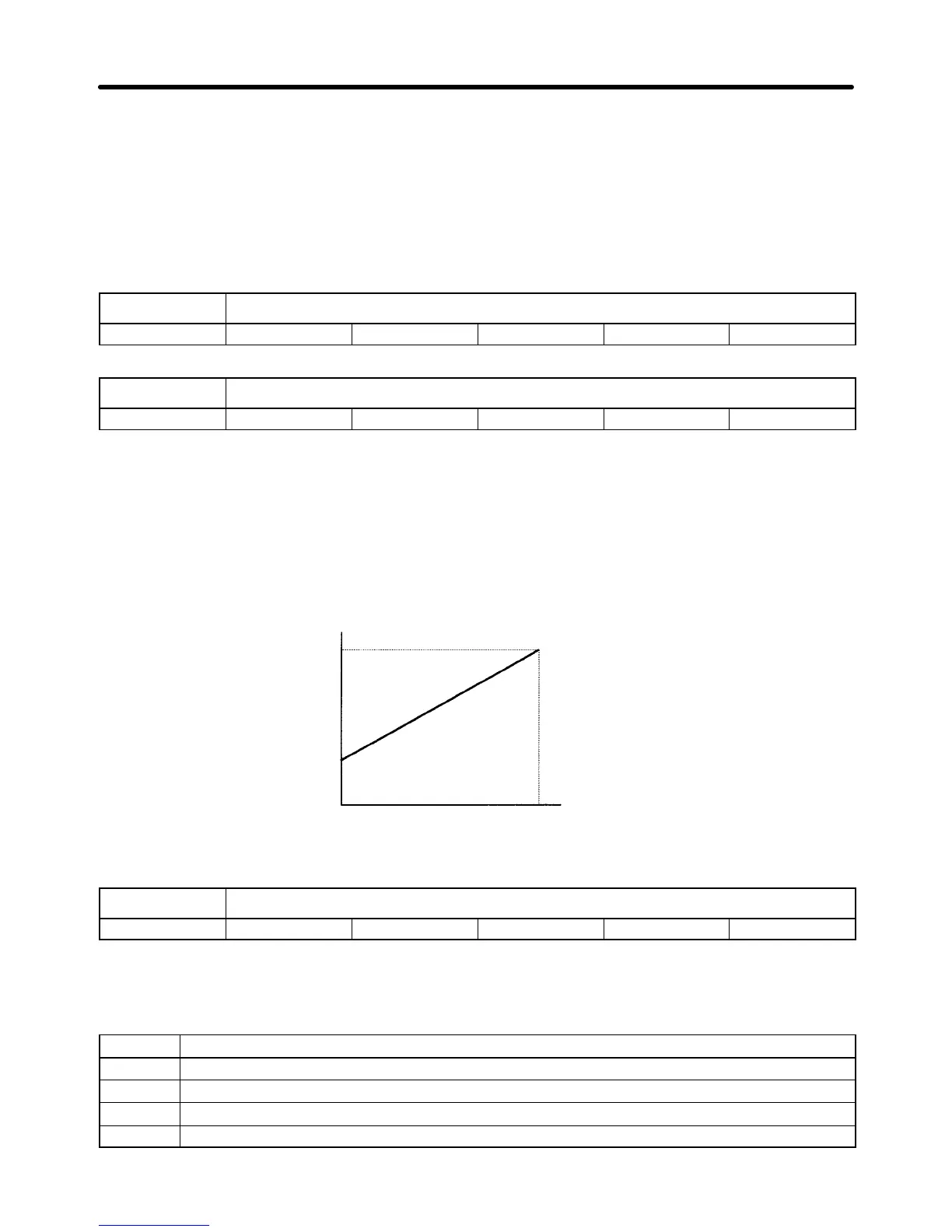
• Set the frequency reference gain with n046 and the frequency reference bias with n047.
Set Values
• n046: The
frequency for 10 V or 20 mA input can be set in 1% units based on the maximum frequency
set with n012 as 100%.
• n047: The
frequency for 0 V or 4
mA input can be set in 1% units based on the maximum frequency
set with n012 as 100%.
Maximum frequency x
frequency reference
gain/100
Maximum frequency x
frequency reference
bias/100
Values in parentheses apply
when the frequency refer-
ence is input with current.
Frequency
reference
0 V
(4 mA)
10 V
(20 mA)
n048 Multi-function Analog Output Selection
Setting range 0, 1, 2, and 3 Unit --- Default setting 0
• Set the n048 so that the type of signal of multi-function analog output terminals AM and AC will be
determined.
Set Values (n048)
Set value Description
0 Output frequency (10 V: Max. frequency n012)
1 Output current (10 V: Rated inverter current)
2 Output power (10 V: Rated inverter output capacity)
3 Main circuit DC voltage (10 V: 200-V class: 400 V; 400-V class: 800V)
Preparing for Operation Chapter 3
 Loading...


