4-13
H Output Frequency Does Not Reach Reference Frequency
• The reference frequency is within the jumping frequency ranges.
The
output frequency
will not change within the jumping frequency ranges if the frequency jump func
-
tion is used.
Check
whether jumping frequency 1 and
2 set with n058 and n059 and the jumping frequency width
set with n060 are proper.
• The reference frequency exceeds the output frequency upper limit.
The output frequency upper limit is obtained from the following.
Maximum frequency (n021) x output frequency upper limit (n 030)/100
Check whether the values set with n012 and n030 are proper.
H Inverter Overload “OL2” is Detected
For
a 400-V Inverter
, if the carrier frequency “n050” is set to a value higher than the default setting, the
Inverter
overload “OL2” detection value will decrease in consideration of an increase in the heat that will
be generated by the change in the carrier frequency. Since the detection value is set to decrease by
approximately 15% for every change to a rank higher than the default setting , the Inverter overload
“OL2” may be detected prior to the motor overload “OL1” depending on the set value. Set the carrier
frequency to a lower level by one rank.
H EF (Forward and Reverse Rotation Commands Input Simultaneously)
is Detected and the Inverter does not Operate
D Incorrect Operation Sequence
If
the forward and reverse commands are input simultaneously for more than 0.5 s, an EF error will be
detected. Change the operation sequence.
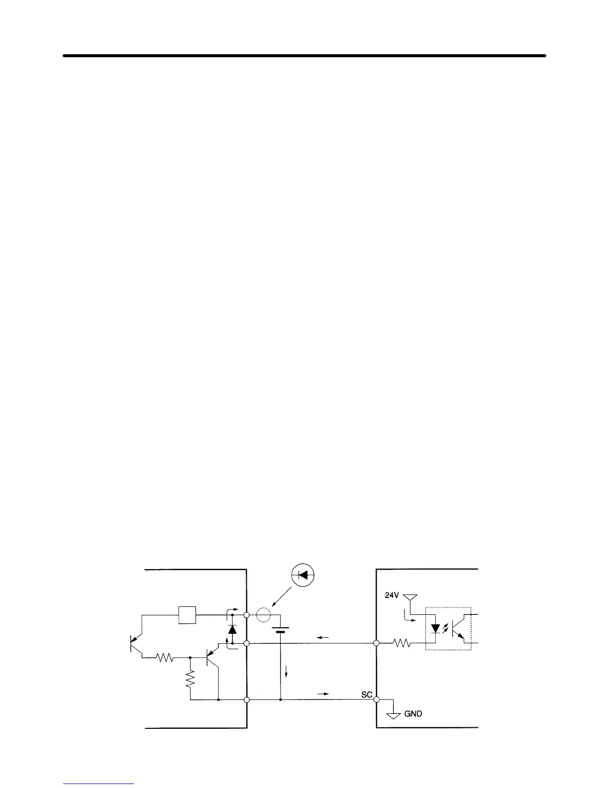
D Malfunction due to Unwanted Current Path
Inverter
inputs may remain ON due to an unwanted current path for the controller outputs.
With the wir
-
ing
shown in the following table, if the controller output power supply is
less than 24 V DC or if the power
is OFF, the current indicated by the arrow will flow and the Inverter inputs will operate. If that occurs,
insert a diode as shown in the diagram at point A.
Control device
A
Inverter (control input)
S1 to 6
Operation Chapter 4
 Loading...


