3-20
S Select
one of the 15 V/f patterns preset with the Inverter
, in which case set n010 to 0, 1, 2, 3, 4, 5,
6, 7, 8, 9, A, b, C, d, or E.
S Set n010 to F for an optional V/f pattern.
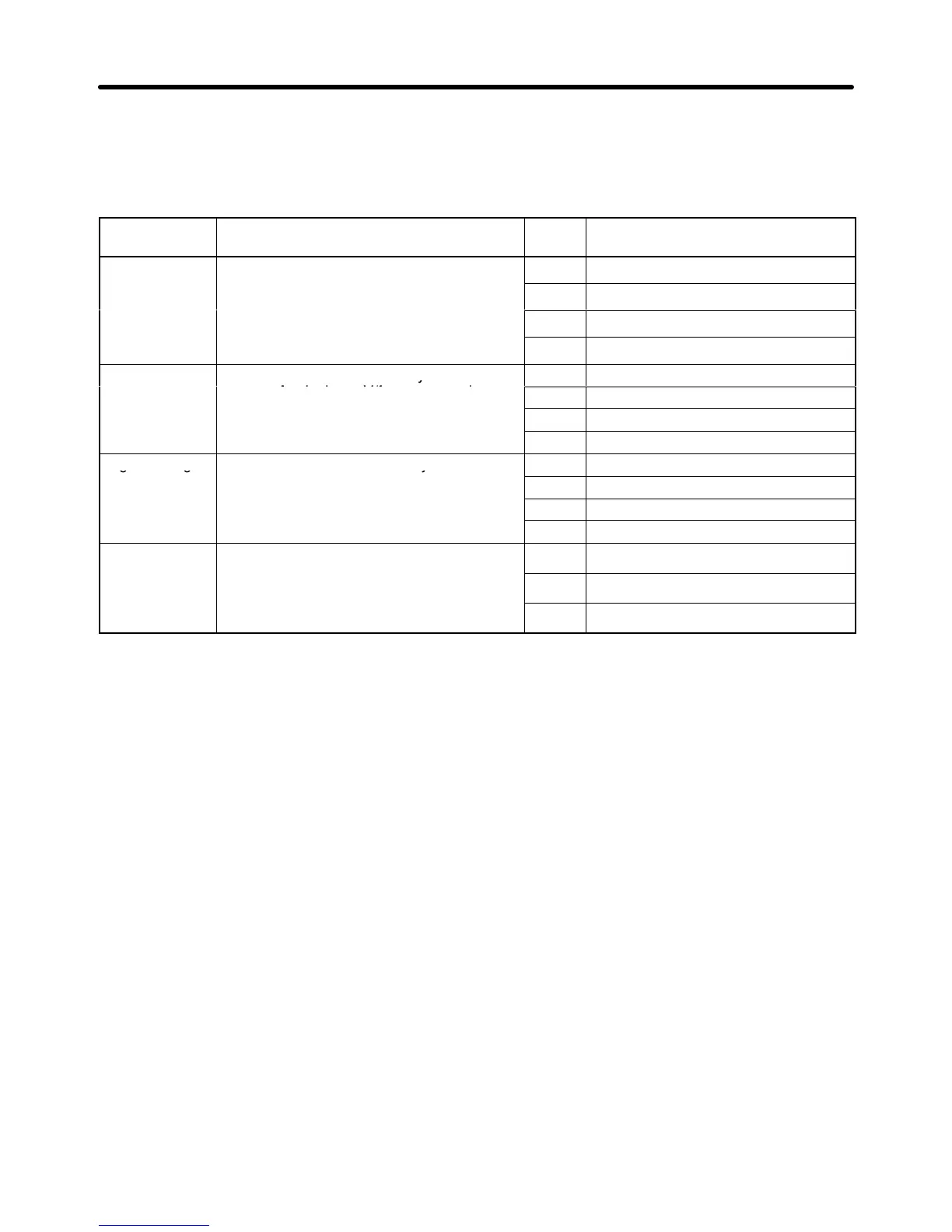
S The following are the V/f patterns preset with the Inverter.
Characteristic Use Set
value
Specification
General
p
These V/f patterns are mainly used for
oses such as the control of
0 50 Hz
purpose general purposes, such as the control of
strai
patterns to the motor if the rotation speed
of the motor must change in almost direct
2 60 Hz. Voltage saturation at 50 Hz.
o
proportion to the load factor of the motor.
3 72 Hz. Voltage saturation at 60 Hz.
Reduced These V/f patterns are mainly used for fan
4 50 Hz with cube reduction.
torque
pumps. Apply these V/f patterns to the
5 50 Hz with square reduction.
motor i
must change in square or cube
6 60 Hz with cube reduction.
must change in square or cube ro ortion
to the load factor of the motor.
7 60 Hz with square reduction.
High starting These V/f patterns are usually
8 50 Hz with low starting torque.
unnecessary because the Inverter has a
full automatic torque boost function to
9 50 Hz with high starting torque.
ull automatic torque boost
ower to meet the starting
A 60 Hz with low starting torque.
su ly enough ower to meet the starting
torque of the motor.
B 60 Hz with high starting torque.
Constant
p
These V/f patterns are used to rotate the
C 90 Hz. Voltage saturation at 60 Hz.
power
operation
mo
y
these V/f patterns to the motor to impose a
D 120 Hz. Voltage saturation at 60 Hz.
constant voltage at 60 Hz minimum on the
motor.
E 180 Hz. Voltage saturation at 60 Hz.
Note 1. Set n010 so that the Inverter will produce high starting torque only in the following cases.
S The wiring distance between the Inverter and the motor is approximately 150 m or more.
S The
motor requires high
starting torque. The motor requires high starting torque if the motor
is connected a vertical-axis load.
S Power is input to or output from the Inverter through an AC or DC reactor.
Note 2. The set values of n012 to n018 will change automatically if any of the patterns listed in the
above table is selected.
Note 3. Refer to the following graphs for the characteristics of the V/f patterns.
The maximum voltage shown in each of the graphs is 200 V. The actual voltage, however,
corresponds to the set value of n011 (i.e., the rated input voltage of the motor). All voltage
values
will
change in proportion to the set value of n01
1. For example, the default-set value of
n011
of
the 400-V Inverter is 400 (V). Therefore, double all the voltage values when using the
400-V Inverter.
Preparing for Operation Chapter 3
 Loading...


