XtraDrive User Manual Chapter 5: Parameter Settings and Functions
5-38
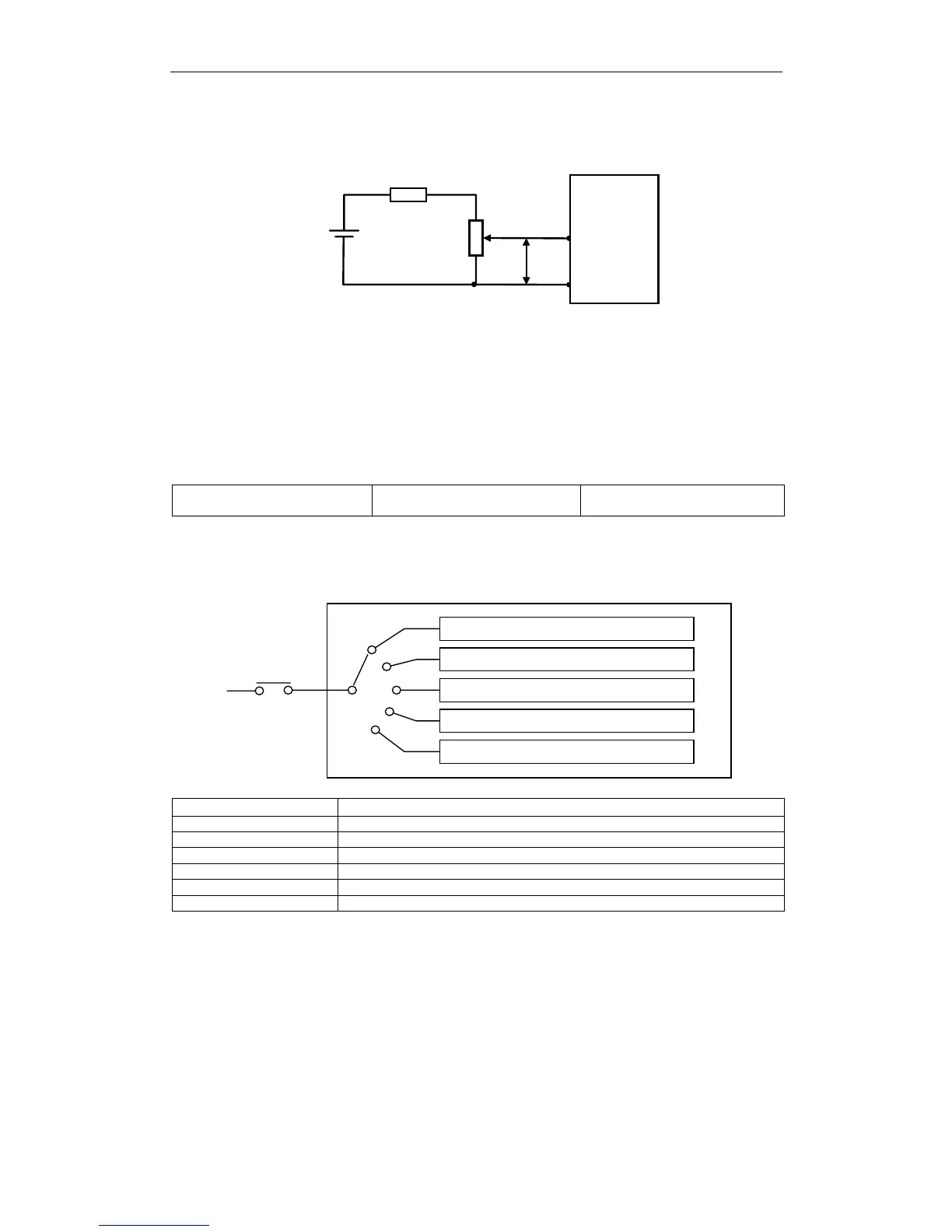
Example of an Input Circuit
+12V
470
Ω
, 1/2W
T-REF
XtraDrive
CN1-9
CN1-10
P
2k
Ω
Note: Always use twisted pair cables for noise control.
Speed Reference Inputs
Refer to Section 5.2.1.
Using the /P-CON Signal
Input /P-CON CN1-41
Proportional Control Reference,
etc.
Speed/Torque Control,
Position Control
The function of the input signal /P-CON varies with the setting applied
to Pn000.1.
P and PI control switching
Zero clamp ON/OFF switching
Inhibit ON/OFF switching
Control mode switching
Direction of rotation switching
Xt r aD ri ve
/P-CON
(Pn000.1)
Pn000.1 Setting /P-CON Function
0, C, D Switches between P (proportional) and PI (proportional-integral) control.
2 Not used.
3, 4, 5, 6 Switches the direction of rotation in Contact Input Speed Control mode.
7, 8, 9 Switches the control mode.
A Turns ON/OFF zero clamp.
B Turns inhibit ON/OFF.
Note: The /P-CON signal function switches automatically when Pn50A.0 is set to 0.