XtraDrive User Manual Appendix A: Host Controller Connection Examples
A-5
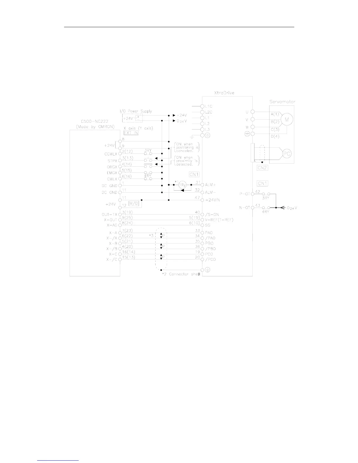
A.4. Connecting OMRON's C500-NC222 Position Control Unit
The following diagram shows an example of connecting to an OMRON
C500-NC222 Position Control Unit. In this example, the servo amplifier is
used in Speed Control Mode.
*1. The ALM signal is output for approximately two seconds when the power is turned ON. Take this into
consideration when designing the power ON sequence. The ALM signal actuates the alarm detection relay 1Ry
to stop main circuit power supply to the XtraDrive.
*2. Connect the shield wire of the I/O cable to the connector shell.
*3. P indicates twisted pair wires.
Note:
Only signals applicable to OMRON's C500NC222 Position Control Unit and YET's XtraDrive are
shown here.