XtraDrive User Manual Chapter 8 : Ratings, Specifications and Dimensional Drawings
8-4
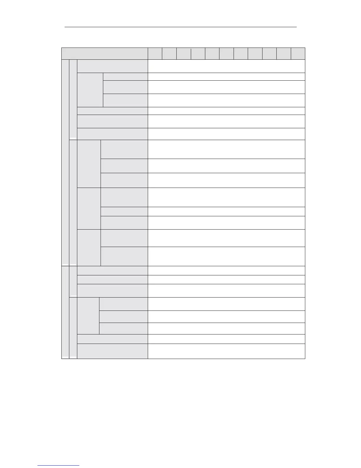
XtraDrive Ratings and Specifications (continued)
XtraDrive Model
XD-
P3 P5 01 02 04 05 08 10 15 20 30
Speed Control Range
1:5000 (The lowest speed of the speed control range is the point just
before the motor stops under full-load condition.)
Load Regulation 0 to 100% load: 0.01% maximum (at rated speed)
Voltage
Regulation
Rated Voltage ±10%: 0% (at rated speed)
Speed
Regulation *
Temperature
Regulation
25 ± 25°C: ±0.1% max. (at rated speed)
Frequency Characteristics 400Hz (at J
L
= J
M
)
Torque Control Tolerance
(Repeatability)
±2%
Performance
Soft Start Time Setting 0 to 10s (Can be set individually for acceleration and deceleration)
Reference
Voltage**
±6V
DC
(Variable setting range: ±2 to ±10V
DC
) at rated torque (positive
torque reference with positive reference), input voltage: ±12V
(maximum).
Input Impedance About 14kΩ
Speed Reference
Input
Circuit Time
Constant
—
Reference
Voltage**
±3V
DC
(Variable setting range: ±1 to ±10V
DC
) at rated torque (positive
torque reference with positive reference), input voltage: ±12V
(maximum)
Input Impedance About 14kΩ
Torque
Reference
Input
Circuit Time
Constant
About 47µs
Rotation Direction
Selection
With P control signal
Speed and Torque Control Modes
Input Signals
Contact
Speed
Reference
Speed Selection
With forward/reverse current limit signal (speed 1 to 3 selection),
servomotor stops or another control method is used when both are
OFF.
Bias Setting 0 to 450rpm (setting resolution: 1rpm)
Feed Forward Compensation 0 to 100% (setting resolution: 1%)
Performa
n
Positioning Completed Width
Setting
0 to 250 reference units (setting resolution: 1 reference unit)
Type
Sign + pulse train, 90° phase difference 2-phase pulse (A phase + B
phase), or CCW + CW pulse train
Form Line driver (+5V level), open collector (+5V or +12V level)
Reference
Pulse
Frequency 500/200kpps maximum (line driver/open collector).
Control Signal Clear Signal (input pulse form identical to reference pulse)
Position Control Mode
Input Signals
Built-in Open-Collector Power
Supply***
+12V (1kΩbuilt-in resistor)
* Speed regulation is defined as follows:
The motor speed may change due to voltage variations or amplifier drift and changes in processing resistance due
to temperature variation. The ratio of speed changes to the rated speed represents speed regulation due to voltage
and temperature variations.
** Forward is clockwise viewed from the non-load side of the servomotor, (counterclockwise viewed from the
load and shaft end).
***The built-in open collector power supply is not electrically isolated from the control circuit in the servo amplifier.