XtraDrive User Manual Chapter 3: Wiring
3-17
3.4.3. I/O Signal Names and Functions
The following section describes servo amplifier I/O signal names and
functions.
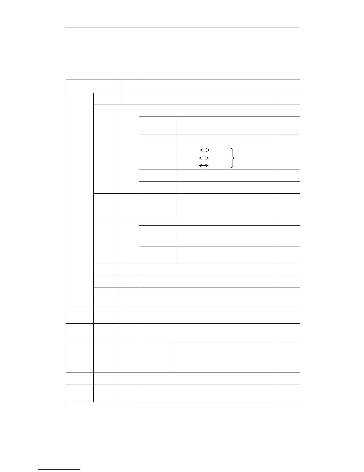
! Input Signals
Signal Name
Pin
No.
Function
Refer-
ence
/S-ON
40
Servo ON: Turns ON the servomotor when the gate block
in the inverter is released.
5.5.2
* Function selected via parameter.
5.2.1
5.2.7
Proportional
operation
reference
Switches the speed control loop from PI
(proportional/integral) to P (proportional)
control when ON.
5.2.1
Direction
reference
With internal reference speed selected:
Switches the direction of rotation.
5.2.6
Position
Speed
Speed
Torque
Control mode
switching
Torque
Speed
Enables
control mode
switching.
5.2.7
Zero-clamp
reference
Speed control with zero-clamp function:
reference speed is zero when ON.
5.4.3
Common
/P-CON
41
Reference
pulse block
Position control with reference pulse stop:
stops reference pulse input when ON.
5.2.10
P-OT
N-OT
42
43
Forward Run
prohibited
Reverse Run
prohibited
Overtravel prohibited: stops servomotor
when movable part travels beyond the
allowable range of motion.
5.1.2
* Function selected with a parameter.
—
Forward
current limit ON
Reverse
current limit ON
Current limit function used when ON.
5.1.3
/P-CL
/N-CL
45
46
Internal
speed
switching
With internal reference speed selected:
switches the internal speed settings.
5.2.6
/ALM
-RST
44
Alarm reset: Releases the servo alarm state.
5.5.1
+24V
IN
47
Control power supply input for sequence signals: users
must provide the +24V power supply.
5.2.4
SEN
4 (2)
Initial data request signal when using an absolute encoder.
5.2.3
BAT+
BAT-
21
22
Connecting pins for the absolute encoder backup battery.
5.2.3
Speed
Referenc
e
V-REF
5 (6)
Speed reference input: ±2 to ±10V/rated motor speed
(Input gain can be modified with a parameter.)
5.2.1
Torque
Referenc
e
T-REF
9
(10)
Torque reference input: ±1 to ±10V/rated motor speed
(Input gain can be modified with a parameter.)
5.2.1
Position
Referenc
e
PULS
/PULS
SIGN
/SIGN
7
8
11
12
Corresponds
to reference
pulse input
Line-driver
Open-
collector
Input mode
•
Code + pulse string
•
CCW/CW pulse
•
Two-phase pulse (90° phase differential)
5.2.1
CLR
/CLR
15
14
Error counter clear: Clears the error counter during
position control.
5.2.1
PL1
PL2
PL3
3
13
18
+12V pull-up power supply when PULS, SIGN and CLR
reference signals is open-collector outputs (+12V power
supply is built into the servo amplifier).
5.2.1
Note: 1. The functions allocated to /S-ON, /P-CON. P-OT, N-OT, /ALM-RST, /P-CL, and /N-CL input
signals can be changed with parameters. (See 5.3.3 Input Circuit Signal Allocation.)
2. Pin numbers in parenthesis ( ) indicate signal grounds.
3. The voltage input range for speed and torque references is a maximum of ±12V.