XtraDrive User Manual Chapter 9 : Inspection, Maintenance, and Troubleshooting
9-4
9.2. Troubleshooting
This section describes causes and remedies for problems, which generate an
alarm display, and for problems, which result in no alarm display.
9.2.1. Troubleshooting Problems with Alarm Displays
Problems that occur in the servo drives are displayed on the panel
operator as “A.##” or “CPF##”. Refer to the following sections to
identify the cause of an alarm and the action to be taken.
Contact YET if the problem has not been solved after following the
described procedures.
Note: “A.- -: Normal Operation”, is not an alarm.
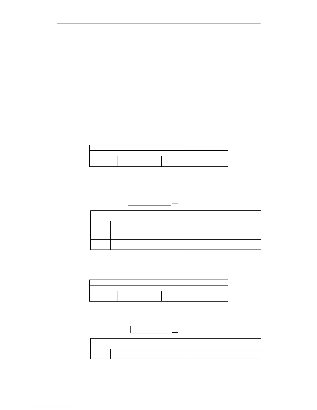
! A.02: Parameter Breakdown
Display and Outputs
Alarm Outputs
Alarm Code Output
ALO1 ALO2 ALO3
ALM Output
OFF OFF OFF OFF
Note: OFF: Output transistor is OFF (alarm state).
Status and Remedy for Alarm
A
At power ON
A
A, B
Cause of the Problem Solution
A
Power turned OFF during parameter
writes. Alarm occurred at next
power ON.
•
Initialize parameters using Fn005
then reenter settings.
•
Replace the servo amplifier.
B Circuit board (1PWB) defective. Replace the servo amplifier.
! A.03: Main Circuit Detection Error
Display and Outputs
Alarm Outputs
Alarm Code Output
ALO1 ALO2 ALO3
ALM Output
OFF OFF OFF OFF
Note: OFF: Output transistor is OFF (alarm state).
Status and Remedy for Alarm
AAt power ONA A
Cause of the Problem Solution
A
Circuit board (1PWB or 2PWB)
defective.
Replace servo amplifier.