XtraDrive User Manual Chapter 5: Parameter Settings and Functions
5-50
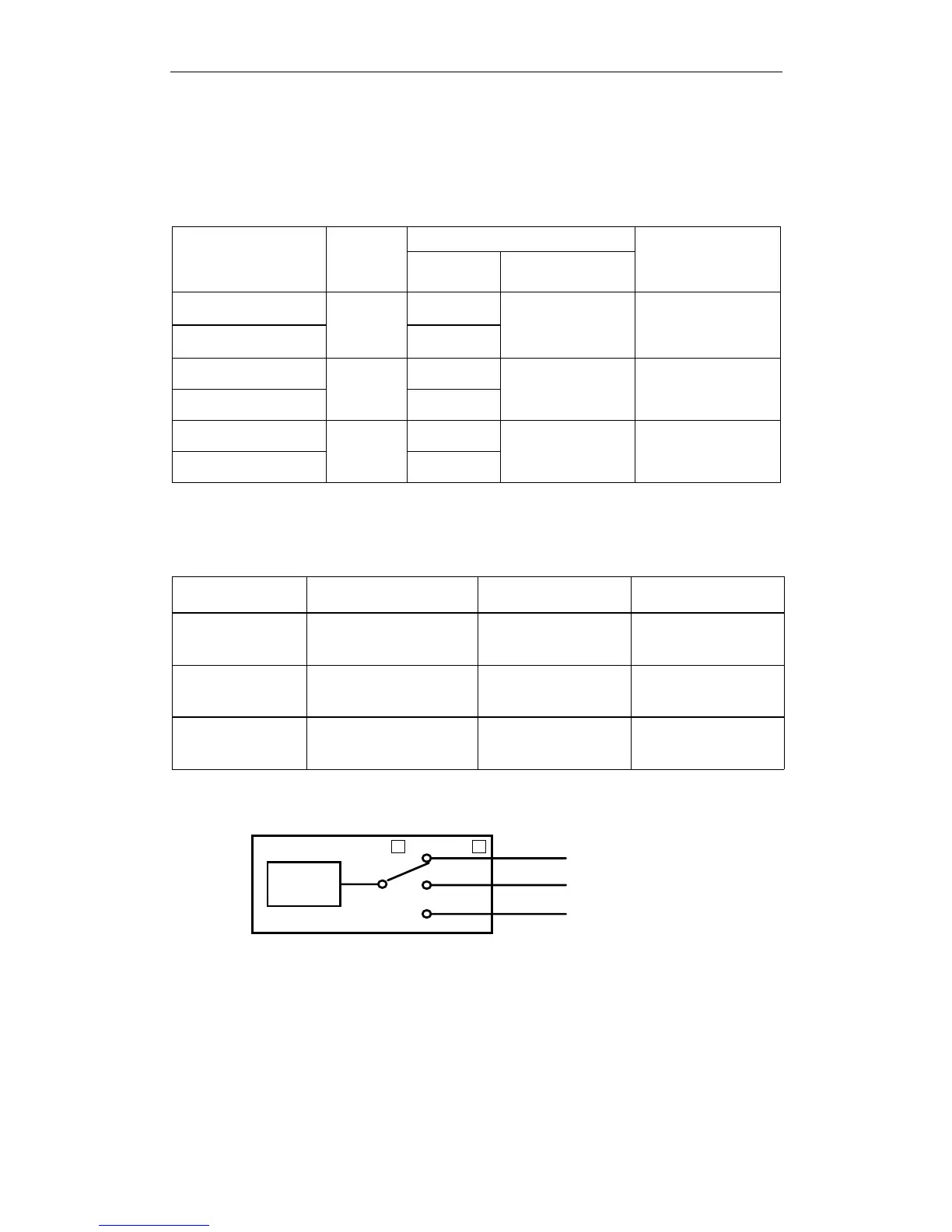
5.3.4. Output Circuit Signal Allocation
Output Signal Allocation
Output signal functions can be allocated to the sequence signal output
circuits shown below.
Default Setting
CN1 Connector
Terminal
Numbers
Output
Terminal
Name
Symbol Name
Comments
25
/V-CMP+
(/COIN+)
26 (SG)
SO1
/V-CMP–
(/COIN–)
Speed coincidence
detection
(positioning
completed)
The signal output
will vary depending
on the control mode.
27 /TGON+
28 (SG)
SO2
/TGON–
Rotation detection —
29 /S-RDY+
30 (SG)
SO3
/S-RDY–
Servo ready —
Output Signal Selection Default Settings
The output signal selection parameters and their default settings are
shown below.
Parameter Signal Setting Description
Pn50E Output Signal Selections 1 Default Setting: 3211
Speed/Torque Control,
Position Control
Pn50F Output Signal Selections 2 Default Setting: 0000
Speed/Torque Control,
Position Control
Pn510 Output Signal Selections 3 Default Setting: 0000
Speed/Torque Control,
Position Control
Select the CN1 connector terminals that will output the signals.
Output
signal
SO1 (CN1-25, 26)
SO2 (CN1-27, 28)
SO3 (CN1-29, 30)
Pn50E. to Pn510.