XtraDrive User Manual Chapter 3: Wiring
3-25
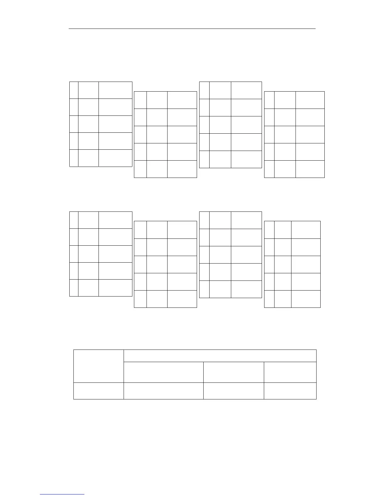
3.5.2. CN2 Encoder Connector Terminal Layout and Types
The following tables describe CN2 connector terminal layout and types.
CN2 Connector Terminal Layout
1 PPG0V PG GND
3 PPG0V PG GND
5 PPG5V PG +5V
7 NC* -
9 /PS
Serial PG
/S-phase
2 PPG0V PG GND
4 PPG5V PG +5V
6 PPG5V PG +5V
8 PS
Serial PG
S-phase
10 SPG5V
Serial PG
+5V
11 SPG0V
Serial PG
GND
13 BAT-
Battery “ –“
input
15 /PC
PG
/C-phase
17 /PA
PG
/A-phase
19 /PB
PG
/B-phase
12 BAT+
Battery ”+”
input
14 PC
PG
C-phase
16 PA
PG
A-phase
18 PB
PG
B-phase
20 NC* -
Note: NC* – Leave contact open.
Optional: CN2 Connector with Commutation Sensors
Terminal Layout
1 PPG0V PG GND
3 PPG0V PG GND
5 PPG5V PG +5V
7 /UIN
U – Phase
Hall Effect
9 /VIN
V – Phase
Hall Effect
2 PPG0V PG GND
4 PPG5V PG +5V
6 PPG5V PG +5V
8 NC* -
10 SPG5V +5V
11 SPG0V GND
13 BAT-
Battery ” –“
input
15 /PC
PG
/C-phase
17 /PA
PG
/A-phase
19 /PB
PG
/B-phase
12 BAT+
Battery “+”
input
14 PC
PG
C-phase
16 PA
PG
A-phase
18 PB
PG
B-phase
20 /WIN
W – Phase
Hall Effect
Note: NC* – Leave contact open.
CN2 Connector Models
Applicable Plug (or Socket)
XtraDrive
Internal
Connector
Soldered Plug Case
Soldered Plug
(Servomotor
Side)
10220-52A2JL
20 PIN
MDR 10120-3000VE 20PIN
(YET P/N: 4J4001)
10320-52A0-008
(YET P/N:
4J0101)
54280-0600 6PIN
(YET P/N: 4J1521)
Note: The motor-end relay socket connects to the encoder connector for the SGMAH and SGMPH
servomotors.