XtraDrive User Manual Chapter 6: Servo Adjustment
6-22
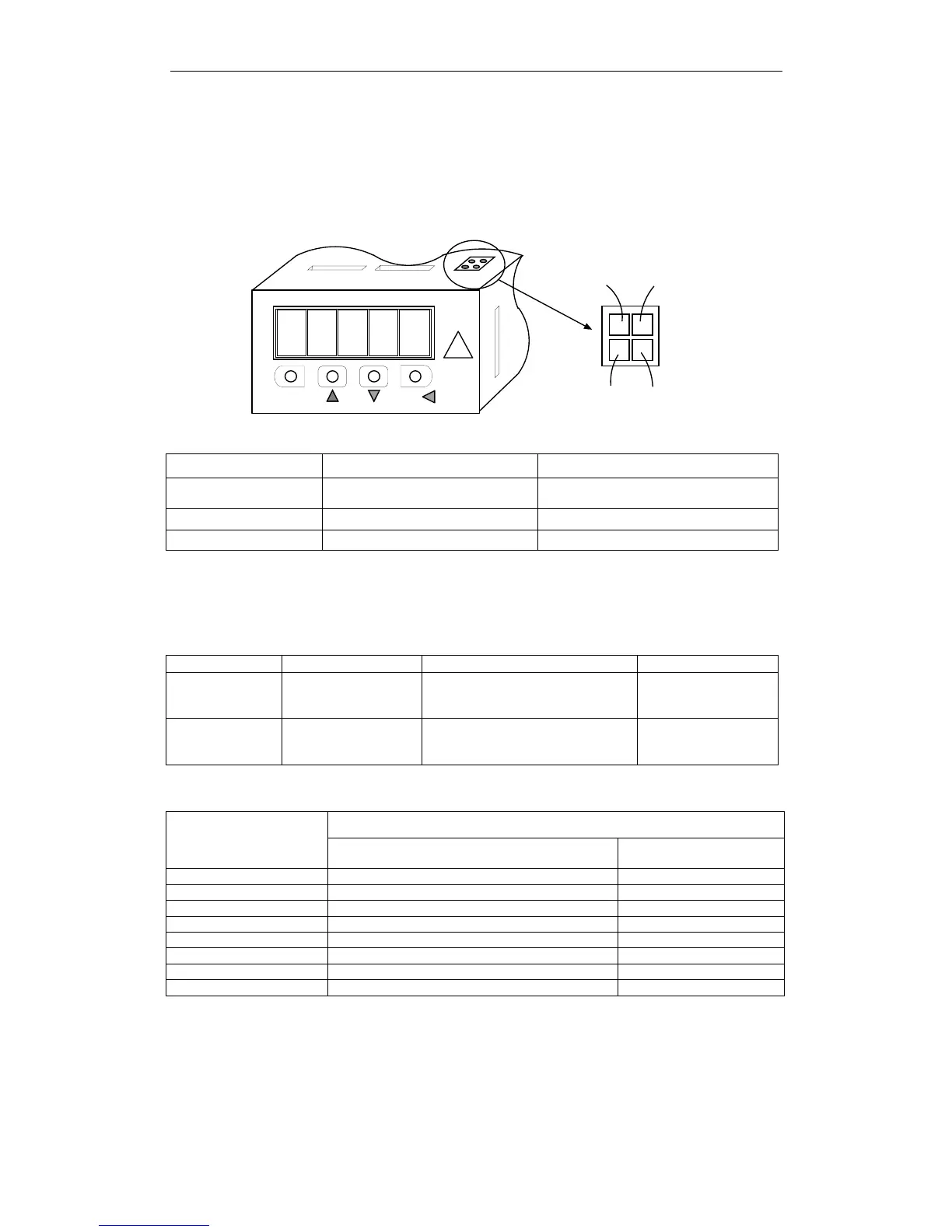
6.4. Analog Monitor
The analog monitor can be used to observe a variety of analog voltage
signals. Analog monitor signals must be observed through the CN5
connector using the Yaskawa P/N DE9404559 cable.
8. 8.8.8.8.
DA TA /MODE/ SET
CN5
Black Black
Red White
Cable Color Signal Name Description
White Analog monitor 1
Torque reference: 1V/100% rated
torque
Red Analog monitor 2 Motor speed: 1V/1000 rpm
Black (two wires) GND (0V) —
Analog monitor signals can be selected with parameters:
Pn003.0 (if Pn006.1=0) and Pn003.1 (if Pn007.1=0) or
Pn006.0 (if Pn006.1=1) and Pn007.0 (if Pn007.1=1).
Parameter Signal Setting Description
Pn003.0 Analog Monitor 1 Default Setting: 2
Speed/Torque
Control,
Position Control
Pn003.1 Analog Monitor 2 Default Setting: 0
Speed/Torque
Control,
Position Control
The following monitor signals can be observed.
Description
Settings in Pn003.0
and Pn003.1
Monitor signal
Observation gain
0 Motor speed 1V / 1000rpm
1 Speed reference 1V / 1000rpm
2 Torque reference 1V / 100% rated torque
3 Position error 0.05V / 1 reference unit
4 Position error 0.05V / 100 reference unit
5 Reference pulse frequency (converted to rpm) 1 V / 1000rpm
6 Motor speed 1 V / 250rpm
7 Motor speed 1 V / 125rpm
Note: 1. In the case of torque or speed control mode, the position error monitor signal has no meaning.
2. The output voltage range of the analog monitor is ±8V maximum. The polarity of the output voltage
will be changed if ±8V is exceeded.