XtraDrive User Manual Chapter 5: Parameter Settings and Functions
5-73
5.6.1. External Regenerative Resistor
When installing an external regenerative resistor, a parameter setting
must be changed as shown below.
Parameter Signal Setting (x 10W)
Description
Pn600
Regenerative
Resistor Capacity
Setting Range: 0 to maximum
Default Setting: 0
Speed/Torque Control,
Position Control
The default setting of “0” in the above table is the set value when the
servo amplifier’s built-in resistor is used or when a servo amplifier
without a built-in resistor is used.
When installing an external regenerative resistor, set the regenerative
resistor’s capacity (W).
Example:
When the external regenerative resistor’s actual consumable capacity is 100W, set the parameter to
“10” (10 x 10W = 100W)
Note: 1. In general, when resistors for power are used at the rated load ratio, the resistor temperature increases
to between 200°C and 300°C. The resistors must be used at or below the rated values.
Check with the manufacturer for the resistor’s load characteristics. Use resistors at no more than 20% of
the rated load ratio with natural convection cooling, and no more than 50% of the rated load ratio with
forced air-cooling. Parameter Pn600 must be set for the derated resistor.
2. Use of resistors with thermal switches is recommended as a safety precaution.
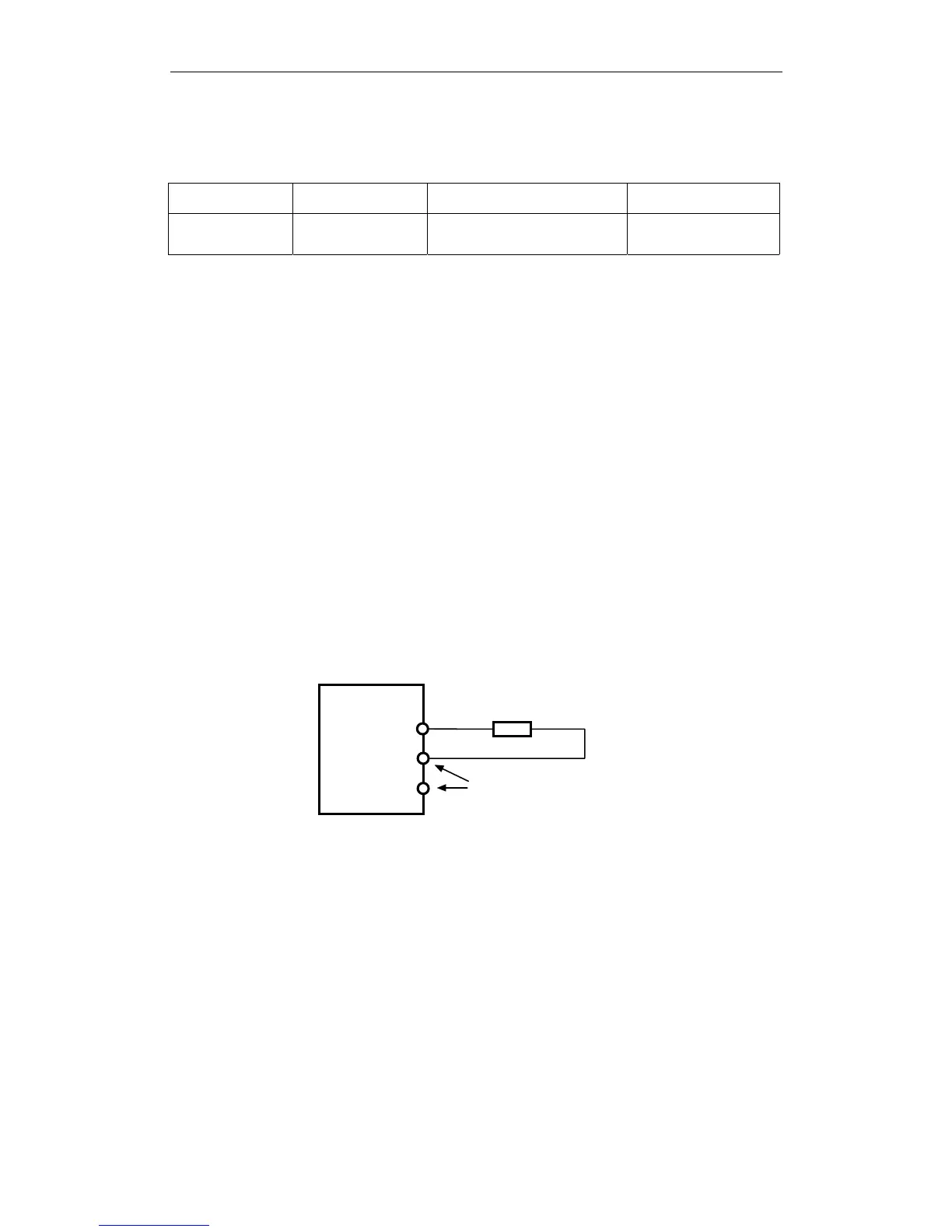
Connecting Regenerative Resistors
The method for connecting regenerative resistors is as follows.
Disconnect the wire between the servo amplifier’s B2 and B3 terminals
and connect an external regenerative resistor between the B1 and B2
terminals.
Regenerative resistor
B1
B2
Xt r a Dri ve
*The user must provide the regenerative resistor.
B3
Be sure to take out the lead wire
between the B2 and B3 terminals.