XtraDrive User Manual Appendix C: Specifications for Peripheral Devices
C-15
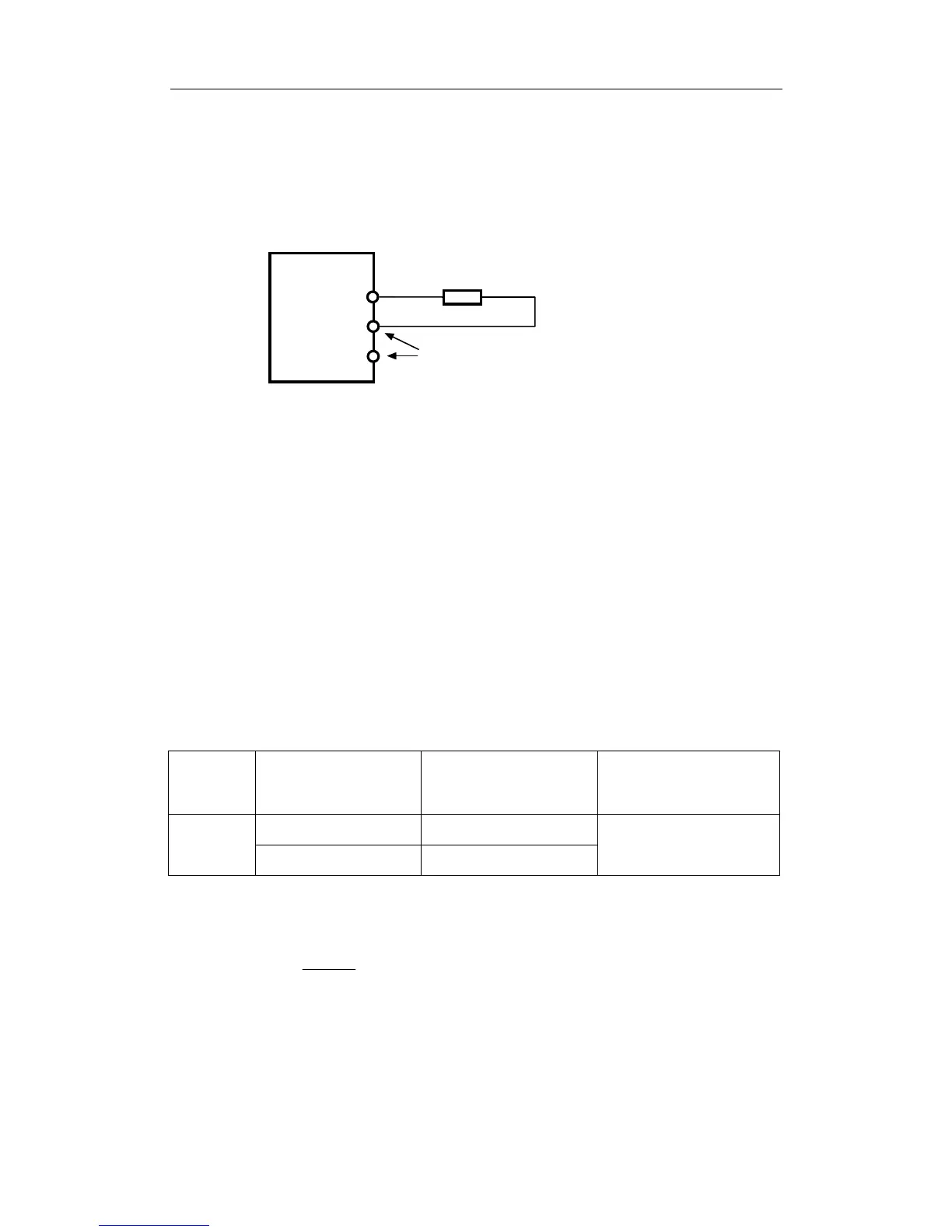
C.12. Connecting Regenerative Resistors
The method for connecting regenerative resistors is shown below.
Disconnect the wire between the servo amplifier’s B2 and B3 terminals and
connect an external regenerative resistor between the B1 and B2 terminals.
Regenerative resistor
B1
B2
Xt r a Dr i ve
*The user must provide the regenerative resistor.
B3
Be sure to take out the lead wire
between the B2 and B3 terminals.
! Calculating the Regenerative Power Capacity
Simple Calculation Method
When driving a servomotor normally along the horizontal axis, check
the external regenerative resistor requirements using the calculation
method shown below.
Servo Amplifiers with Capacity of 400W or Less
Servo amplifiers with a capacity of 400W or less do not have built-in
regenerative resistors. The energy that can be absorbed by capacitors is
shown in the following table. If the rotational energy in the servo
system exceeds these values, then connect a regenerative resistor
externally.
Voltage
Applicable Servo
Amplifiers
Regenerative Energy
that Can be Processed
(joules)
Comments
XD-P3-**, -P5-** 18.5
200V
XD-01-** to -04-** 37.1
Value when the input voltage
is 200V AC
Calculate the rotational energy in the servo system using the following
equation:
E
S
=
()
12566
Nx J
2
M
Joules
Where: J = J
M
+ J
L
J
M
: Servomotor rotor inertia (kg·m
2
) (oz·in·s
2
)
J
L
: Motor axis conversion load inertia (kg·m
2
) (oz·in·s
2
)
N
M
: Rotation speed of the servomotor (rpm)