XtraDrive User Manual Chapter 3: Wiring
3-28
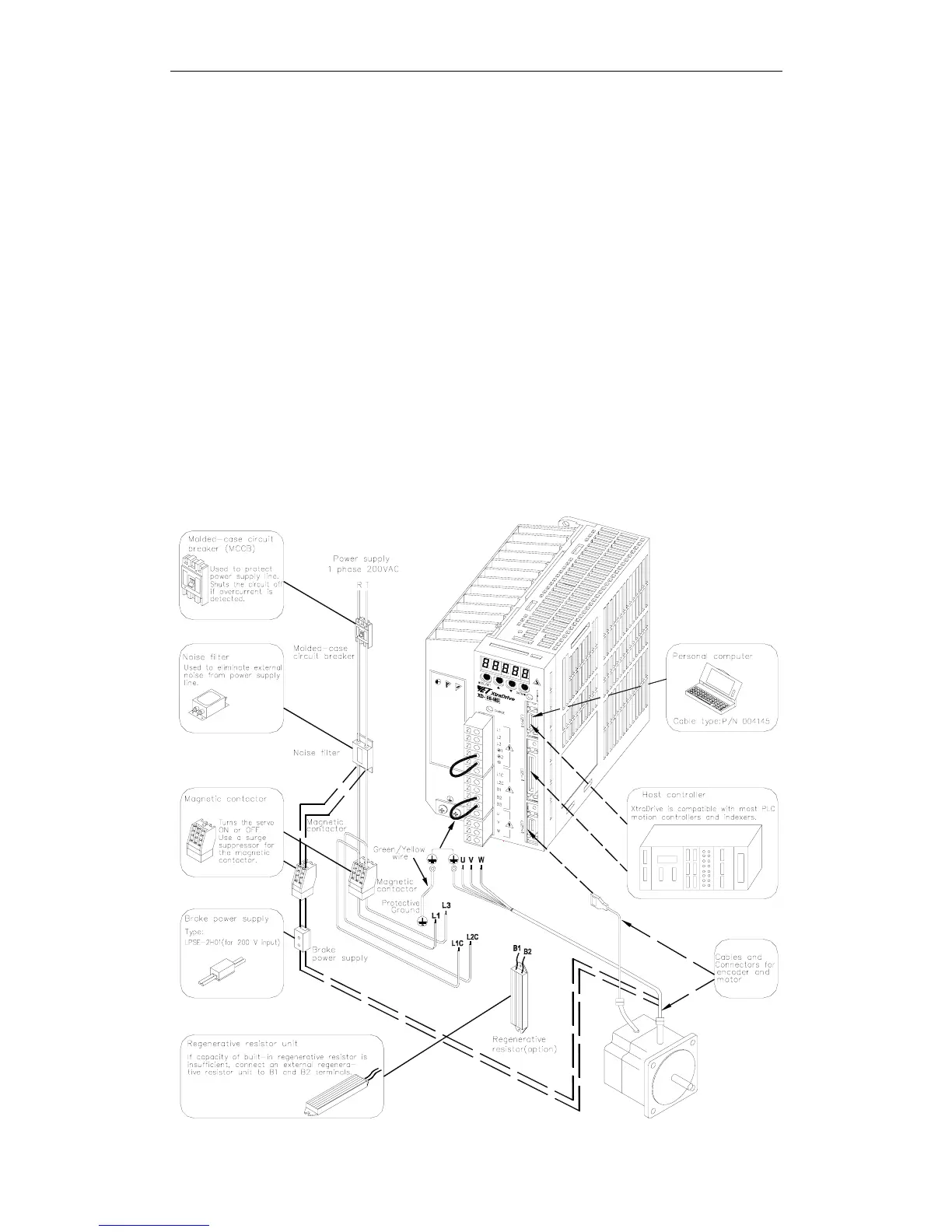
3.6. Examples of Standard Connections
The following diagrams show examples of standard servo amplifier
connections by specifications and type of control.
Note for single-phase power supply specifications:
XtraDrive XD-08** have changed from three-phase specifications to single-
phase. Main circuit connection terminals (L1, L2, L3) remained.
These devices have terminal B3 and internal regenerative resistor. Observe
the following points.
1. Connect main power supply shown below to L1 and L3 terminals. Power
supply is single-phase, 220 to 230 VAC +10% to –15%, 50/60Hz. If
power supply of 187V (-15% of220V) or less is used, alarm A41
indicating voltage shortage, may occur when accelerating to max speed
with max torque of motor.
2. Short-circuit B2 and B3 terminals using the internal regenerative resistor.
If capacity of the regenerative resistor is insufficient, remove the lead
between B2 and B3 terminals and connect an external regenerative
resistor unit to B1 and B2 terminals.