XtraDrive User Manual Chapter 3: Wiring
3-13
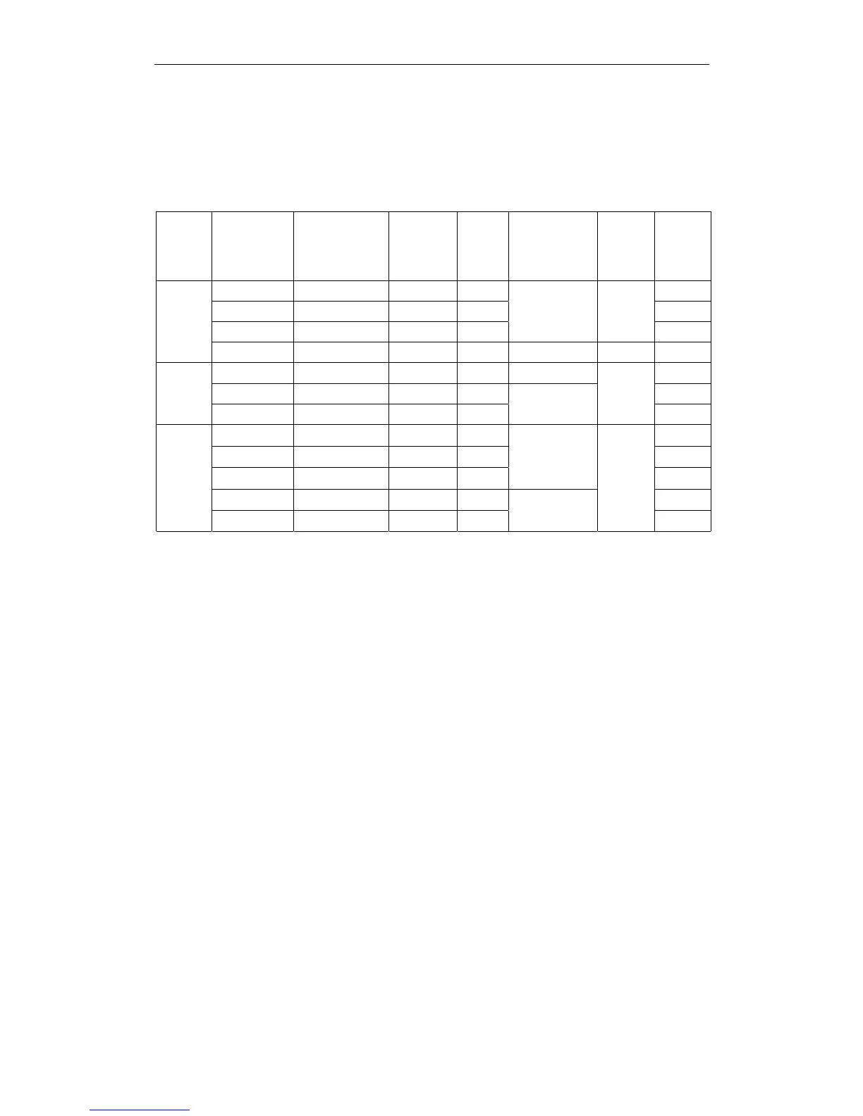
3.3.3. Servo Amplifier Power Losses
The following table shows servo amplifier power losses at the rated
output.
Table
3.2: Servo Amplifier Power Losses at Rated Output
Main
Circuit
Power
Supply
Maximum
Applicable
Servomotor
Capacity
[kW]
Servo Amplifier
Model
Output
Current
(Effective
Value) [A]
Main
Circuit
Power
Loss
[W]
Regenerative
Resistor
Power Loss
[W]
Control
Circuit
Power
Loss
[W]
Total
Power
Loss
[W]
0.10 XD-01-** 0.91 6.7 19.7
0.20 XD-02-** 2.1 13.3 26.3
0.40 XD-04-** 2.8 20
— 13
33
Single-
phase
200V
0.75 XD-08-** 4.4 47 12 15 74
1.0 XD-10-** 7.6 55 12 82
2.0 XD-20-** 18.5 120 163
Three-
phase
200V
3.0 XD-30-** 7.5 60
28
15
198
0.45 XD-05-** 1.9 19 48
1.0 XD-10-** 3.5 35 64
1.5 XD-15-** 5.4 53
14
82
2.0 XD-20-** 8.4 83 161
Three-
phase
400V
3.0 XD-30-** 11.9 118
28
15
243
Note: Regenerative resistor power losses are allowable losses. Take the following action if this value is
exceeded:
• Disconnect the internal regenerative resistor in the servo amplifier by removing the wire
between terminals B2 and B3.
•
Install an external regenerative resistor between terminals B1 and B2.
See 5.6 Selecting a Regenerative Resistor for more details on the resistors.