XtraDrive User Manual Appendix A: Host Controller Connection Examples
A-4
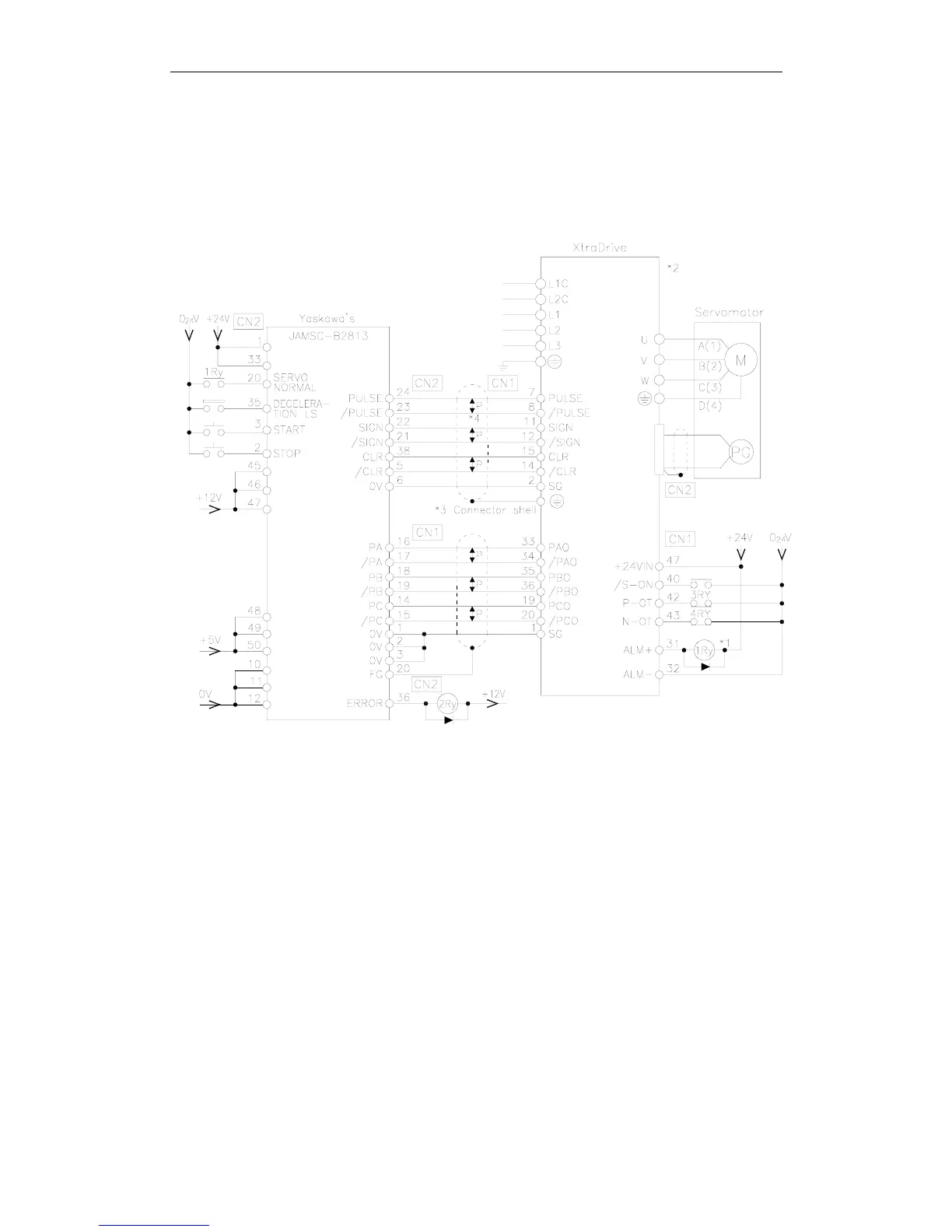
A.3. Connecting the GL-series B2813 Positioning Module
The following diagram shows an example of connecting to the GL-series
B2813 Positioning Module. In this example, the servo amplifier is used in
Position Control Mode.
*1. The ALM signal is output for approximately two seconds when the power is turned ON. Take this into
consideration when designing the power ON sequence. The ALM signal actuates the alarm detection relay 1Ry
to stop main circuit power supply to the XtraDrive.
*2. Set parameter Pn200.0 to “1”.
*3. Connect the shield wire to the connector shell.
*4. P indicates twisted pair wires.