XtraDrive User Manual Chapter 3: Wiring
3-19
3.4.4. Interface Circuits
This section shows examples of servo amplifier I/O signal connection to
the host controller.
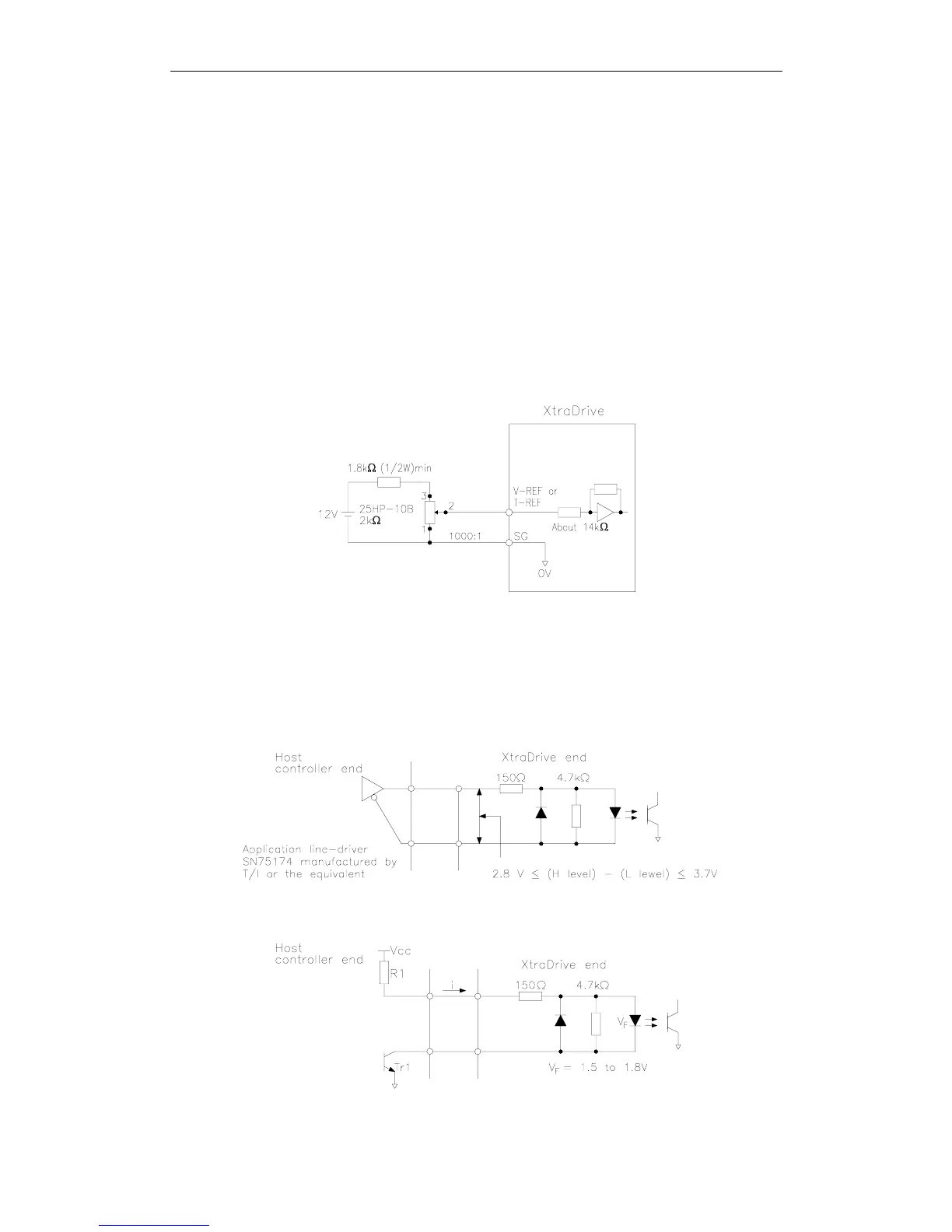
! Interface for Reference Input Circuits
Analog Input Circuit
Analog signals are either speed or torque reference signals at the
impedance below.
• Speed reference input: About 14kΩ
• Torque reference input: About 14kΩ
The maximum allowable voltage for input signals is ±12V.
Reference Position Input Circuit
An output circuit for the reference pulse and error counter clear signal
at the host controller can be either line-driver or open-collector outputs.
These are shown below by type.
• Line-driver Output Example:
• Open-collector Output, Example 1: External power supply