XtraDrive User Manual Chapter 3: Wiring
3-20
The following examples show how to select the pull-up resistor R1 so
the input current (I) falls between 7 and 15mA.
Application Examples
R1 =2.2kΩ with
V
CC
= 24V ±5%
R1 =1kΩ with
V
CC
= 12V ±5%
R1 =180Ω with
V
CC
= 5V ±5%
• Open-collector Output, Example 2: Using a servo amplifier with an
internal 12V power supply
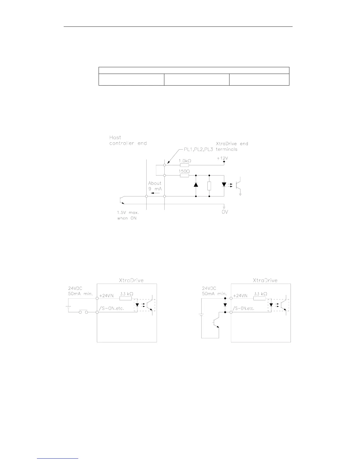
This circuit uses the 12V power supply built into the servo
amplifier. The input is not isolated in this case.
! Sequence Input Circuit Interface
The sequence input circuit interface connects through a relay or open-
collector transistor circuit. Select a low-current relay; otherwise a faulty
contact will result.