XtraDrive User Manual Chapter 3: Wiring
3-21
! Output Circuit Interfaces
Any of the following three types of servo amplifier output circuits can
be used. Connect an input circuit at the host controller following one of
these types.
• Connecting to a Line-driver Output Circuit
Encoder serial data converted to two-phase (A and B phase) pulse
output signals (PAO, /PAO, PBO, /PBO), origin pulse signals (PCO,
/PCO) and S phase rotation signals (PCO, /PCO) are output via line-
driver output circuits that normally comprise the position control
system at the host controller. Connect the line-driver output circuit
through a line receiver circuit at the host controller.
See 3.5 Wiring Encoders for connection circuit examples.
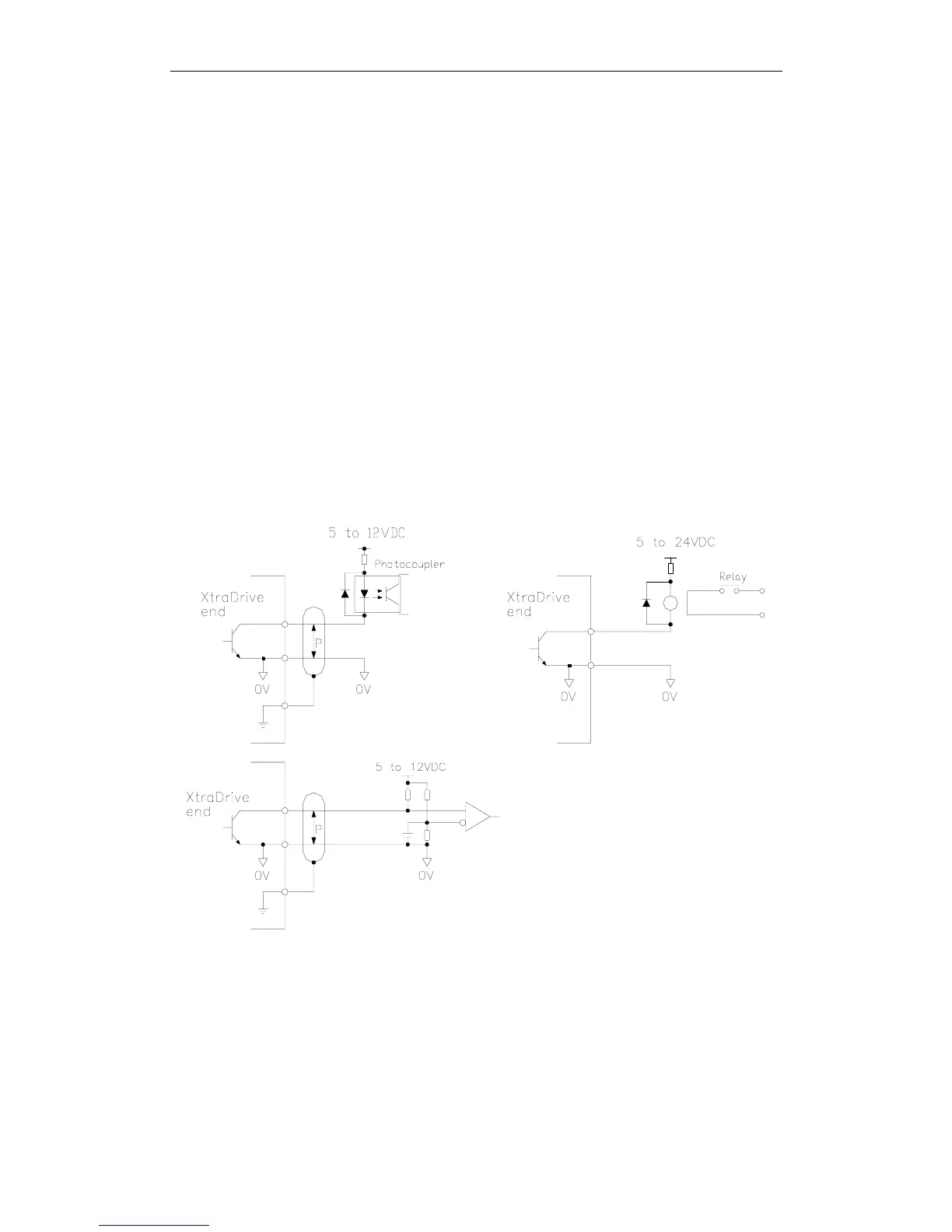
• Connecting to an Open-collector Output Circuit
Alarm code signals are output from open-collector transistor output
circuits.
Connect an open-collector output circuit through an optocoupler,
relay, or line receiver circuit.
Note: The maximum allowable voltage and current capacities for open-collector circuits are:
• Voltage: 30V
DC
• Current: 20mA
DC