XtraDrive User Manual Chapter 5: Parameter Settings and Functions
5-64
CN1-40
(/S-ON)
The external short-circuit wiring shown
in the figure can be omitted if the Servo
ON (/S-ON) input signal is not used.
Xt r a Dr i ve
0V
Pn50A.1
Setting
Status Result
0
Enables the servo ON
(/S-ON) input signal.
The servo is OFF when CN-40 is open and ON when
CN1-40 is at 0V.
7
Disables the servo ON
(/S-ON) input signal.
The servo is always ON and has the same effect as
shorting CN1-40 to 0V.
Note: See 5.3.3 Input Circuit Signal Allocation for other Pn50A.1 settings.
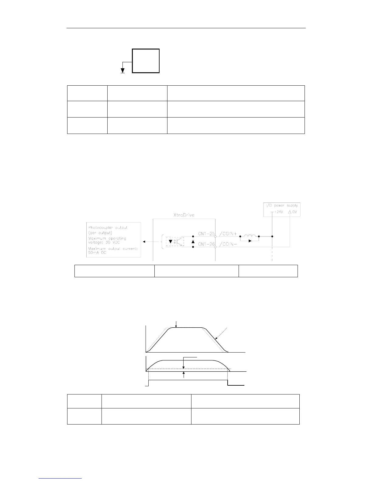
5.5.3. Using the Positioning Completed Output Signal (/COIN)
This section describes the basic use and wiring procedures for the
positioning completed (/COIN) output signal (photocoupler output
signal). The signal is output to indicate that servomotor operation is
completed.
Output /COIN CN1-25
Positioning Completed Output
Signal
Position Control
This signal indicates that the servomotor movement during position
control has been completed. The host controller uses the signal as an
interlock to confirm that positioning is completed.
Reference speed
Speed
Motor speed
Time
Error pulse
(Un008)
/COIN
(CN1-25)
Pn500
/COIN
State
Status
Result
ON
Circuit between CN1-25 and 26 is
closed, and CN1-25 is at low level.
Positioning is completed.
(Position error is below the setting.)