XtraDrive User Manual Chapter 5: Parameter Settings and Functions
5-62
The user must provide a suitable external I/O power supply separately
because there is no internal 24V power supply in the servo amplifier.
The use of the photocoupler output signals is described below.
Output ALM+ CN1-31 Servo Alarm Output
Speed/Torque Control,
Position Control
Output ALM- CN1-32 Signal Ground for Servo Alarm Output
Speed/Torque Control,
Position Control
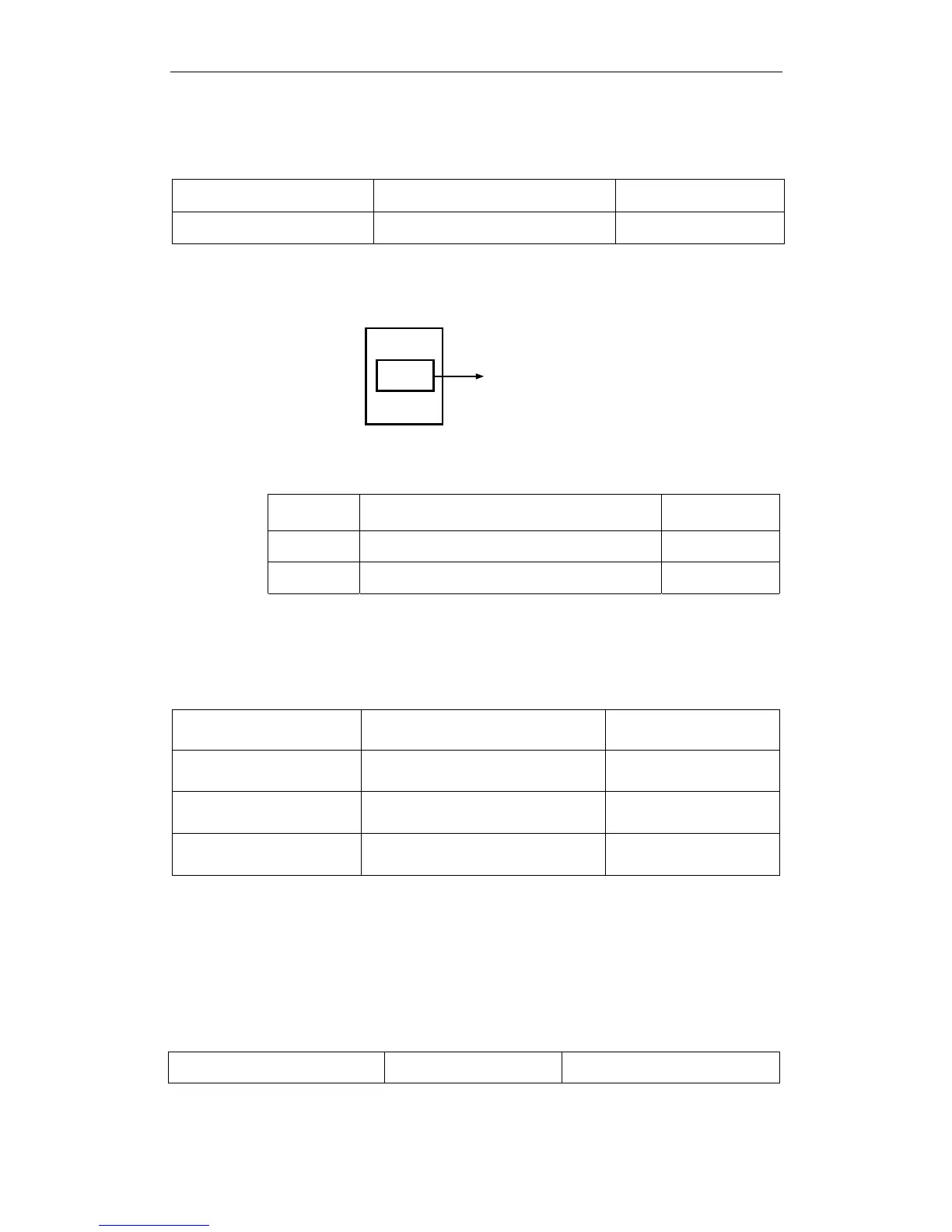
These alarms are output when a servo amplifier alarm is detected.
ALM output
Turns power OFF.
Alarm
detection
Xt ra Dr i ve
Form an external circuit so that this alarm output (ALM) turns OFF the
servo amplifier.
State Status Result
ON
Circuit between CN1-31 and 32 is closed, and
CN1-31 is at low level.
Normal state.
OFF
Circuit between CN1-31 and 32 is open, and
CN1-31 is at high level.
Alarm state.
Alarm codes ALO1, ALO2 and ALO3 are output to indicate each alarm
type.
The use of open-collector output signals ALO1, ALO2, and ALO3 is
described below.
Output ALO1 CN1-37 Alarm Code Output
Speed/Torque Control,
Position Control
Output ALO2 CN1-38 Alarm Code Output
Speed/Torque Control,
Position Control
Output ALO3 CN1-39 Alarm Code Output
Speed/Torque Control,
Position Control
Output /SG CN1-1 Signal Ground for Alarm Code Output
Speed/Torque Control,
Position Control
These signals output alarm codes to indicate the type of alarm detected
by the servo amplifier. Use these signals to display alarm codes at the
host controller. See 9.2.3 Alarm Display Table for more on the
relationship between alarm display and alarm code output.
When a servo alarm (ALM) occurs, eliminate the cause of the alarm and
set the following /ALM-RST input signal to high level (ON) to reset the
alarm.
Input /ALM-RST CN1-44 Alarm Reset
Speed/Torque Control, Position
Control
The Alarm Reset signal is used to reset a servo alarm.