XtraDrive User Manual Chapter 9 : Inspection, Maintenance, and Troubleshooting
9-7
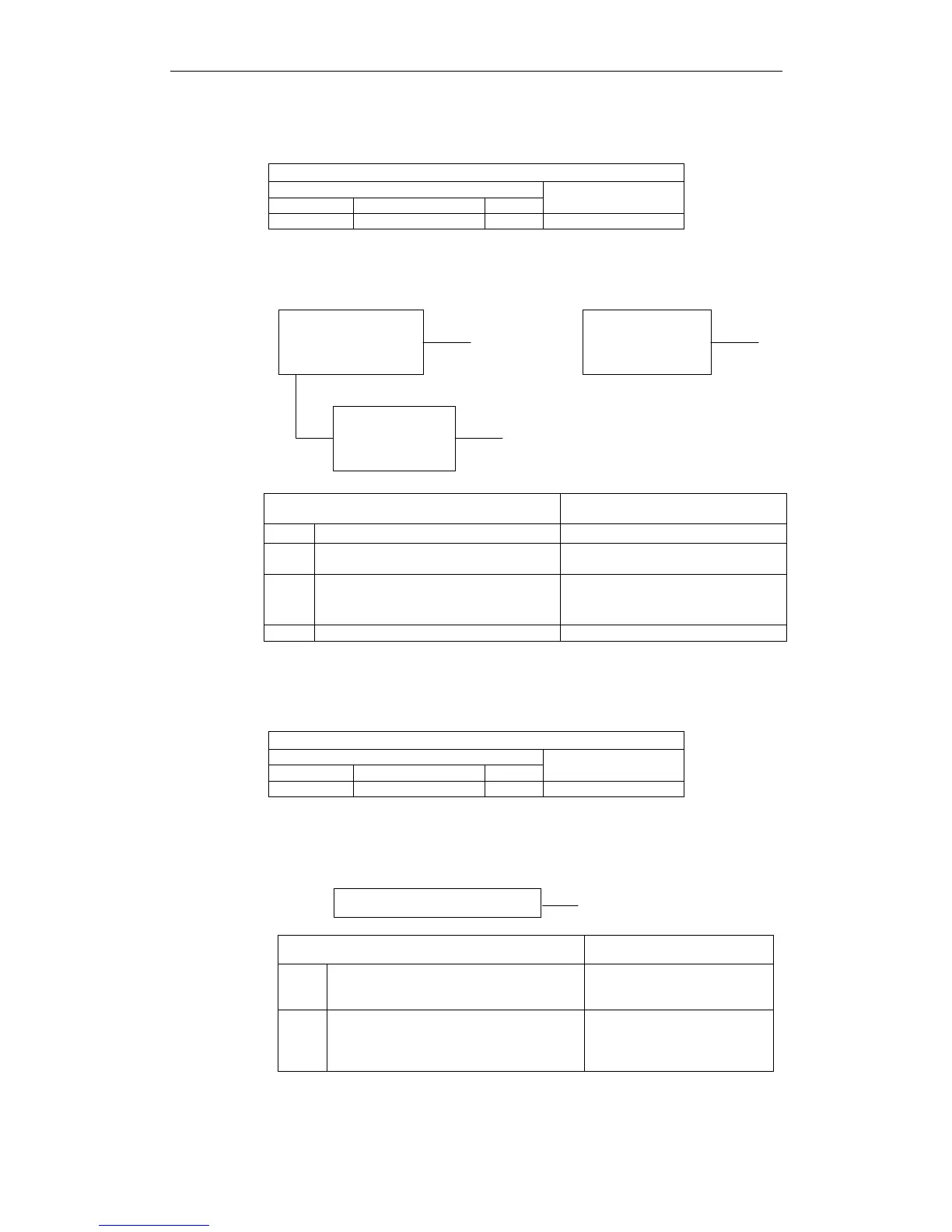
! A.30: Regenerative Error Detected
Display and Outputs
Alarm Outputs
Alarm Code Output
ALO1 ALO2 ALO3
ALM Output
ON ON OFF OFF
Note: OFF: Output transistor is OFF (alarm state).
ON: Output transistor is ON.
Status and Remedy for Alarm
During servomotor
operation
About 1s after
main circuit power
is turned ON.
When the control
power is turned ON.
A, B
D
A, B, C
Cause of the Problem Solution
A Malfunctioning regenerative transistor. Replace servo amplifier.
B Regenerative resistor is open.
Replace servo amplifier or
regenerative resistor.
C
Disconnected regenerative unit (for an
external regenerative resistor).
Check the wiring of the external
regenerative resistor.
D Defective servo amplifier. Replace servo amplifier.
! A.32: Regenerative Overload
Display and Outputs
Alarm Outputs
Alarm Code Output
ALO1 ALO2 ALO3
ALM Output
ON ON OFF OFF
Note: OFF: Output transistor is OFF (alarm state).
ON: Output transistor is ON.
Status and Remedy for Alarm
A
During
servomotor operation
A
A,B
Cause of the Problem Solution
A Regenerative power exceeds the limit.
Use an external regenerative
resistor that matches the
regenerative power capacity.
B
Alarm occurs although an external
regenerative resistor is used and the
temperature rise of the regenerative
resistor is small.
Correct parameter Pn600.