XtraDrive User Manual Appendix D: List of Parameters
D-10
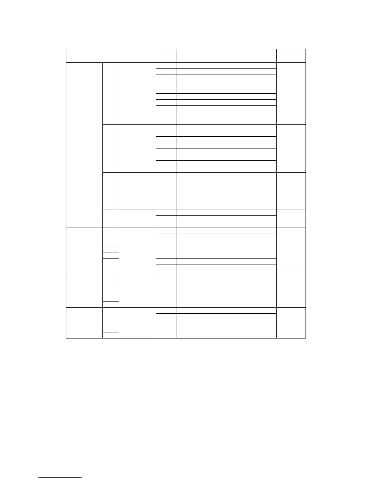
Parameter
Digit
Place
Name
Setting
Description
Default
Setting
0 Sign + pulse, positive logic.
1 CW + CCW, positive logic.
2 A phase + B phase (x1), positive logic.
3 A phase + B phase (x2), positive logic.
4 A phase + B phase (x4), positive logic.
5 Sign + pulse, negative logic.
6 CW + CCW, negative logic.
7 A phase + B phase (x1), negative logic.
8 A phase + B phase (x2), negative logic.
0
Reference
Pulse Form
9 A phase + B phase (x4), negative logic.
0
0
Clears error counter when the signal goes
high.
1
Clears error counter at the rising edge of
the signal.
2
Clears error counter when the signal goes
low.
1
Error Counter
Clear Signal
Form
3
Clears error counter at the falling edge of
the signal.
0
0 Clears error counter at the base block.
1
Does not clear error counter. (Possible to
clear error
counter only with CLR signal).
2 Clears error counter when an alarm occurs.
2
Clear
Operation
3 Clear signal ignore
0
0 Reference input filter for line driver signals.
Pn200
Position Control References Selection Switches
3 Filter Selection
1
Reference input filter for open collector
signals.
0
0 Doesn’t use check sum
0 Check Sum
1 Use check sum
1
1
2
3
--- ---
1 Normally open
Pn2C6
Communication
Switch
Not used
2 Home failure
0
0 OCA is not activate
0
Oscillation
Canceling
Mode
1 OCA is active
1
2
Pn2D4
Oscillation
Canceling
Mode Switch
3
Not used. — —
0
0 Disabled.
0
Notch Filter
Selection
1 Uses a notch filter for torque reference.
1
2
Pn408
Torque
Control
Function
Switches
3
Not used. — —
0