XtraDrive User Manual Chapter 5: Parameter Settings and Functions
5-11
The following output signals and monitor methods are used when
torque is being limited.
Signal Description
/CLT
Generated when Pn50F.0 is allocated to an
output terminal from SO1 to SO3.
Monitor Mode (Un006) —
•
Un005: Numbers 6 and 7 (with default
settings)
Refer to 7.1.6 Operation in Monitor Mode.
•
Un006: Depending on output signal
allocation conditions.
—
Application Examples:
• Forced stop
• Robot holding a workpiece
Parameter Signal Setting (%) Control Mode
Pn404 Forward External Torque Limit
Range: 0 to 800
Default Setting: 100
Speed/Torque
Control, Position
Control
Pn405 Reverse External Torque Limit
Range: 0 to 800
Default Setting: 100
Speed/Torque
Control,
Position Control
Set the torque limits when the torque is limited by an external contact
input.
Signal Description
/P-CL (CN1-45) Input Pn404 torque limit applied.
/N-CL (CN1-46) Input Pn405 torque limit applied.
See 5.2.9 Torque Limiting by Analog Voltage Reference.
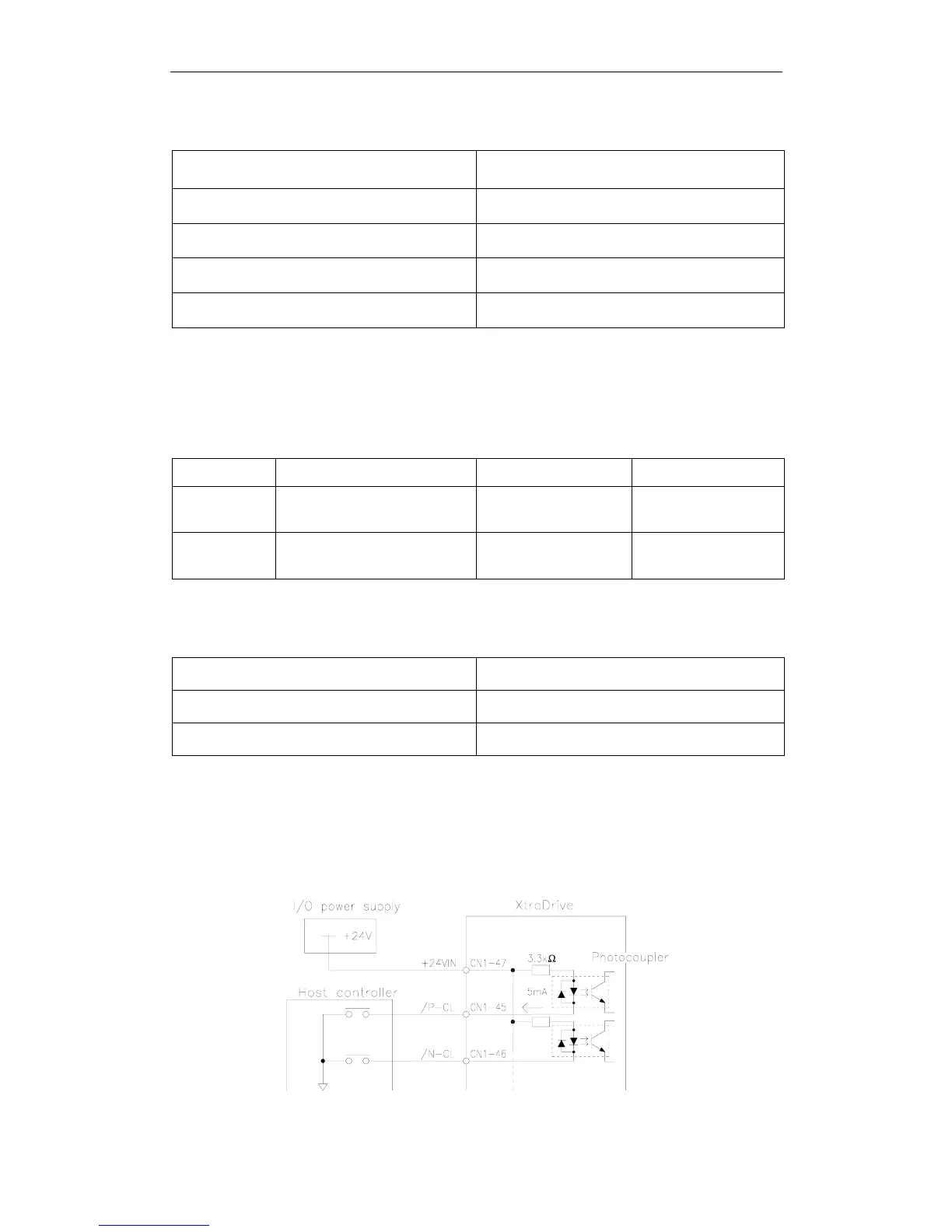
Using /P-CL and /N-CL Signals
The procedure for using /P-CL and /N-CL as torque limit input signals
is illustrated below.