XtraDrive User Manual Chapter 5: Parameter Settings and Functions
5-13
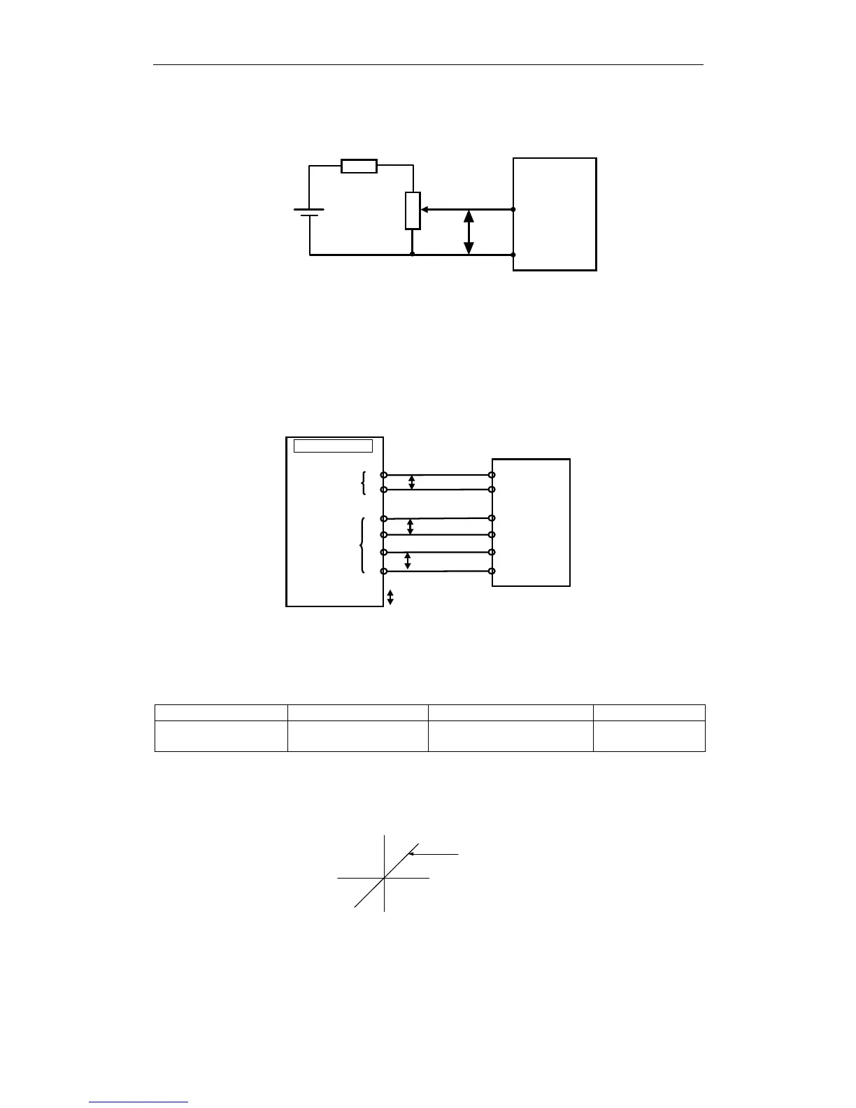
Input Circuit Example
P
V-REF
2k
Ω
470
Ω
, 1/2W min.
+12V
SG
CN1-5
CN1-6
XtraDrive
Always use twisted pair cable for noise control.
Recommended variable resistor: Model 25HP-10B manufactured by
Sakae Tsushin Kogyo Co., Ltd.
Connect V-REF and SG to the speed reference output terminals on the
host controller when using a host controller, such as a programmable
controller, for position control.
CN1-5
CN1-6
XtraDrive
CN1-33
CN1-34
CN1-35
CN1-36
V-REF
SG
P
PAO
/PAO
PBO
/PBO
P
P
Speed
reference
output
terminals
Feedback
pulse input
terminals
Host controller
P: Indicates twisted-pair wires
Adjust Pn300 according to the output voltage specifications of the host
controller.
Adjust the speed reference input adjustment factor in the following
parameter.
Parameter Signal Setting Control Mode
Pn300
Speed Reference Input
Adjustment Factor
Range: 150 to 3000 x
(0.01V/ rated motor speed)
Speed Control
Set the voltage range for the V-REF speed reference input at CN1-5
according to the host controller and external circuit output range.
Set this slope
Reference
speed (rpm)
Reference
voltage (V)
The default setting is adjusted so that a 6V input is equivalent to the
rated motor speed of all applicable servomotors.
Note: The maximum allowable voltage to the speed reference input (between CN1-5 and 6) is ± 12V
DC
.