XtraDrive User Manual Chapter 5: Parameter Settings and Functions
5-16
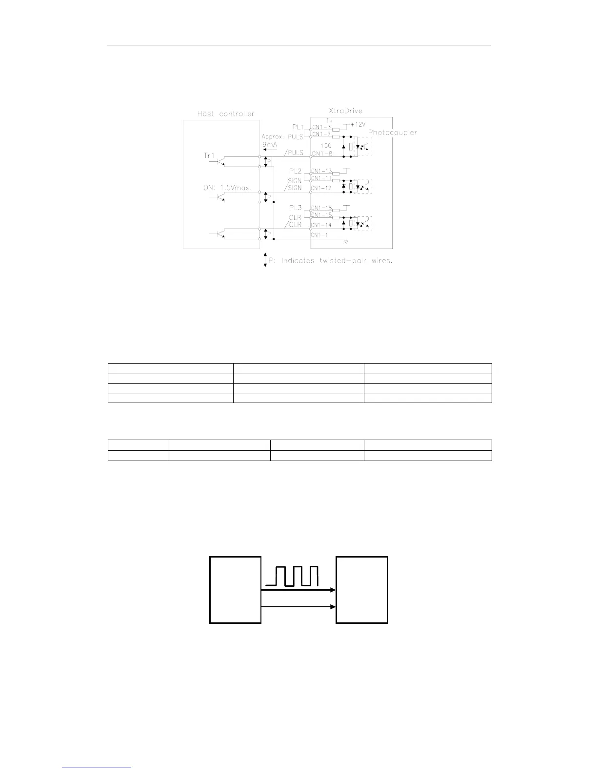
This circuit uses the 12V power supply built into the servo amplifier.
The input is not isolated in this case.
Ω
Ω
Note:
The noise margin of the input signal will decrease if the reference pulse is provided by an open-
collector output. Set parameter Pn200.3 to 1 if the position drifts due to noise.
Selecting a Reference Pulse Form
Use the following parameters to select the reference pulse form used.
Input PULS CN1-7 Reference Pulse Input Position Control
Input /PULS CN1-8 Reference Pulse Input Position Control
Input SIGN CN1-11 Reference Code Input Position Control
Input /SIGN CN1-12 Reference Code Input Position Control
The servomotor only rotates at an angle proportional to the input pulse.
Parameter Signal Setting Range Control Mode
Pn200.0 Reference Pulse Form Default Setting: 0 Position Control
Set reference pulse form input to the servo amplifier from the host
controller.
Note: This function works only with a Pulse Reference, not with a Serial Command.
CN1-7
CN1-11
PULSE
SIGN
Position
reference
pulse
Xt r aD ri ve
Host
controller
Since the reference pulse form can be selected from among those listed
below, set one according to host controller specifications.