XtraDrive User Manual Chapter 5: Parameter Settings and Functions
5-18
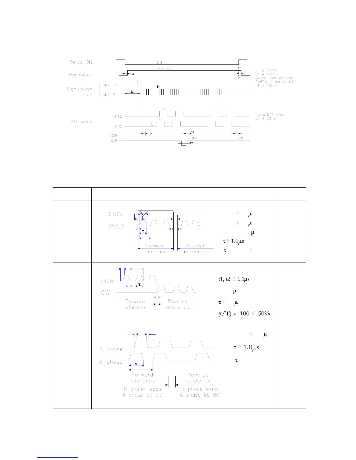
Example of I/O Signal Generation Timing
t2
t6
µ
Note: 1.
For the input pulse to register, the interval from the time the servo ON signal is turned ON until a
reference pulse is entered must be a minimum of 40ms.
2.
The error counter clear signal must be ON for at least 20µs.
Reference Pulse Input Signal Timing
Reference
Pulse Form
Electrical Specifications Remarks
Sign + pulse
train input
(SIGN +
PULS signal)
Maximum
reference
frequency:
500kpps
(200kpps
open-collector
output)
t7
t1, t2 0.1 s
t4, t5, t6 > 3 s
t3, t7 0.1 s
t3
t4
T
t6t5
( /T) x 100 50