XtraDrive User Manual Chapter 5: Parameter Settings and Functions
5-21
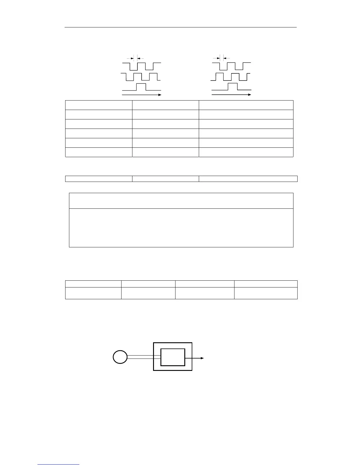
Output Phase Form
t
t
Reverse
rotation
Forward
rotation
90
°
90
°
Input SEN CN1-4 SEN Signal Input Speed/Torque Control
Input /SEN CN1-2 Signal Ground Speed/Torque Control
Output PSO CN1-48 Encoder Output Phase S Speed/Torque Control, Position Control
Output /PSO CN1-49 Encoder Output Phase /S Speed/Torque Control, Position Control
Input BAT (+) CN1-21 Battery (+) Speed/Torque Control, Position Control
Input /BAT (-) CN1-22 Battery (-) Speed/Torque Control, Position Control
Use SEN to BAT (-) signals for absolute encoders. See 5.7 Absolute Encoders for
more details.
Output SG CN1-1 Signal ground Speed/Torque Control, Position Control
SG: Connect to 0V on the host controller.
IMPORTANT
•
When using the servo amplifier phase C pulse signal to return to the machine origin,
always turn the servomotor at least twice before starting the original return operation.
If the configuration of the mechanical system prevents turning the servomotor before the
origin return operation, then perform the origin return operation at a servomotor speed of
600rpm or below. The phase C pulse signal may not be correctly applied if the servomotor
turns faster than 600rpm.
Pulse Divider Setting
Set the pulse dividing ratio in the following parameter:
Parameter Signal Setting (PPR) Control Mode
Pn201 PG Divider
Range: 0 to 65535
Default Setting: 2048
Speed/Torque Control,
Position Control
Serial encoder
Set the number of pulses for PG output signals (PAO, /PAO, PBO,
/PBO).
Xt r aD ri ve
Frequency
division
Encoder
PG
Phase A
Phase B
Serial
data
Output
Output terminals: PAO (CN1-33)
/PAO (CN1-34)
PBO (CN1-35)
/PBO (CN1-36)
Pulses from the servomotor encoder (PG) are divided by the preset
number before being output.
The number of output pulses per revolution is set by this parameter. Set
the value using the reference units of the equipment or the controller
used.
The setting range varies with the encoder used.