XtraDrive User Manual Chapter 5: Parameter Settings and Functions
5-24
Contact input signals: /S-ON (CN1-40)
/P-CON (CN1-41)
P-OT (CN1-42)
N-OT (CN1-43)
/ALM-RST (CN1-44)
/P-CL (CN1-45)
/N-CL (CN1-46)
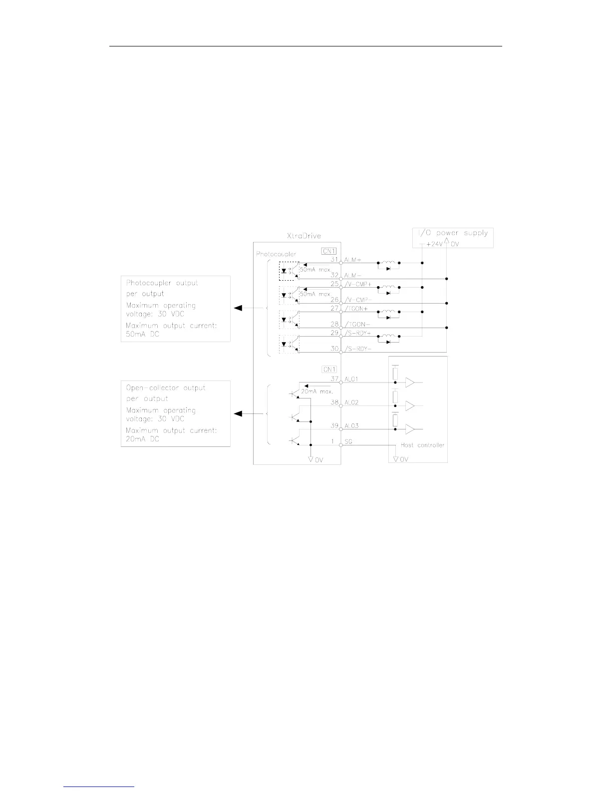
Output Signal Connections
Connect the sequence output signals as shown in the following figure.
Note: Provide a separate external I/O power supply; the servo amplifier does not have an internal 24V power
supply. It is recommended to use the same type of external power supply as the one used for input
circuits.
Function allocation for some sequence output signal circuits can be
changed.
See 5.3.4 Output Circuit Signal Allocation for more details.