Previous Page Table of Contents Section Contents
Back
Index Next Page
LIFEPAK 20/20e Defibrillator/Monitor Replacement Procedures
Boardstack (continued)
Boardstack Installation
(continued)
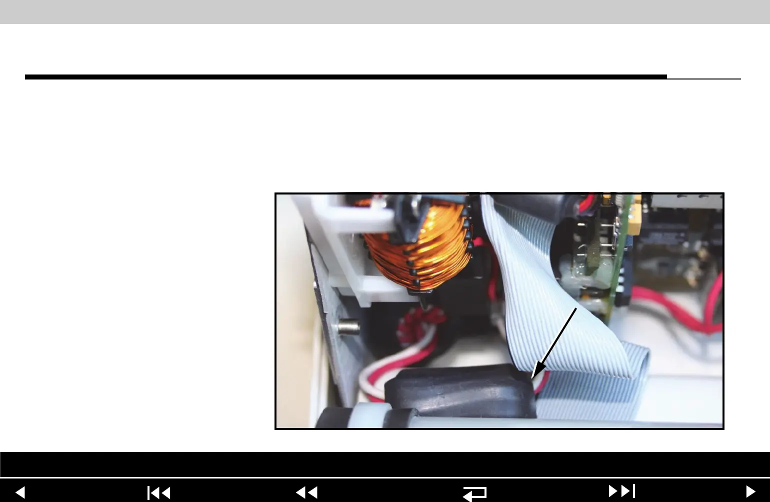
8. Connect the 5-pin therapy connector to the A04 Therapy PCB at J13. Route
three ferrite beads of the 5-pin therapy connector cable into the lower left
corner of the A04 therapy PCB.
Note: If the 5-pin therapy connector cable has a fourth ferrite bead,
(MIN 3200474-009 (RoHS) or 3200474-008 (non-RoHS)), route this bead
above the battery well, prior to connecting to J13
Parts Lists Interconnect System View Therapy View Main Assemblies
9-76