Because RFL™ and Hubbell® have a policy of continuous product improvement, we reserve the right to change designs and specifications without notice.
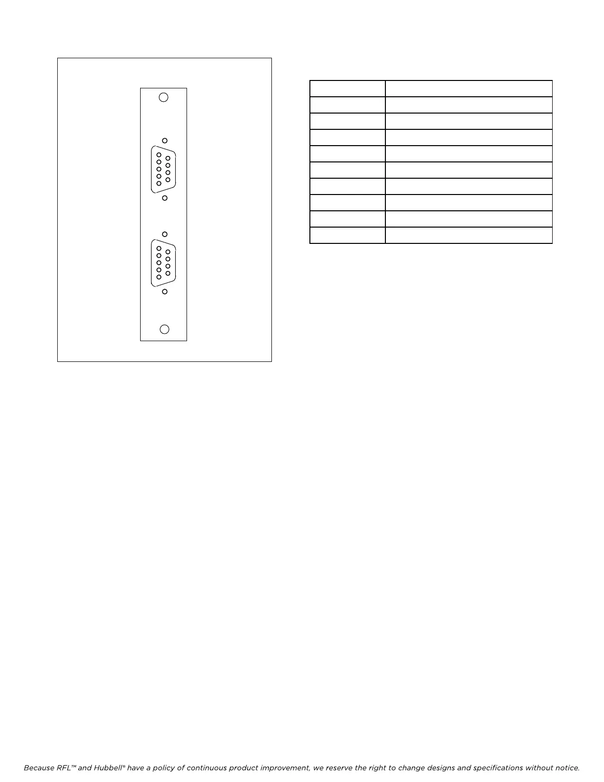
Table 1. Wiring assignments, MA-402I Module
Adapter
RFL DA-91I RFL Electronics Inc.
Ma
rch 6, 2002 4 (973) 334-3100
Pin No. Signal Name
1 Receive Line Signal Detect
2 Receive Data
3 Transmit Data
4 Not used
5 Signal Ground
6 Data Set Ready
7 Request To Send
8 Clear To Send
9 Not used
MA402I
CH1
CH2
1
6
9
5
1
6
9
5
Figure 1. MA-402I Module Adapter
6. Set the module address using DIP switches SW1-1 through SW1-6 for the desired remote
address (SCB address).
For remote access, each channel module in the IMUX 2000 must have a distinct
module address. Valid addresses are the numbers “1” to “36”. In most
installations the address will be set to the number of the slot the module is
occupying. Table 2 shows the switch settings for the module address. (Consult
your multiplexer manual for details on using the remote access and configuration
features of the system).
7. Select an unused time slot for channel 1 using DIP switches SW2-1 through SW2-5. Each
active voice channel uses one 64 Kbps digital time slot within the multiplexer’s aggregate rate.
Set the time slot using direct binary coding as shown in Table 4. Refer to the multiplexer
manual for guidelines on time slot selection.
Note that selecting an invalid time slot will disable the module. In T1 systems, only time slots 1
through 24 are allowed.
In E1 systems, time slots 1 through 31 are allowed, however, time slots 0 and 16 are reserved
and cannot be used.
8. Set DIP switch SW2-6 to enable or disable CAS (channel associated signaling).
Place SW2-6 in the UP position to disable signaling
Place SW2-6 in the DOWN position to enable signaling